Today I will try to introduce you to the H bridges.
The H-bridge is an electrical system that allows you to change the direction of a DC motor by reversing the polarity of the voltage at its output. Such a bridge can be made of e.g. relays, transistors or a ready-made integrated circuit can be used.
The name comes from the graphic representation of the layout. Such a bridge is made of 4 contacts which are switched in pairs.
Below is a graphic representation of the H.
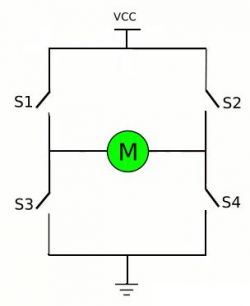
The contact S1 and S4 form one pair and the contact S2 and S3 form the second pair. Switching on one pair of S1-S4 results in a positive potential on the left pole of the motor and negative on the right pole. Switching on the second pair, S2-S3, causes the reversal of this polarity, which changes the direction of the current flow and, as a result, the direction of rotation of the motor.
Building an H bridge on relays is quite simple and does not require complicated control. However, this solution has some disadvantages - contact resistance, contact life and its number of contacts. By adding a transistor to this system, we gain an additional function thanks to which we can regulate the speed of the motor powered from such a bridge.
You can also use bipolar transistors or MOSfets to build bridges.
With the above-mentioned bridges, it should be noted that during their control, a certain state appears which can be said to be forbidden, i.e. we cannot control all our contacts at the same time, we can only control pairs S1-S4 or S2-S3, otherwise the system will create short circuit.
H bridges are used quite often, for example, in the construction of sumo, micromouse or linefolower robots, they can also be found in power steering systems in cars.
A bit of theory behind us so we already know what it is and what it is for. Now we can take care of our layout on the subject. The L298 is a double H-bridge in a Mulitwatt 15 housing. The word "double" here means that in one housing we have two separate bridges, which will allow us to operate two DC motors.
The module discussed here is a ready-to-use system where, after connecting the power supply and connecting the engine, we can start playing with the engine.
Below is a photo and description of the connectors and outputs of this module.
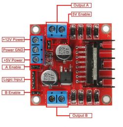
Below is a diagram of the module.

As you can see from the photos and the diagram, we have two power supplies here - one to power the motor, the other to power the bridge logic. The manufacturer of the board stated that the logic power supply is 5VDC and the motors are 12VDC. Looking at the documentation, we can find that the logic power supply can be 4.5-7VDC and the power supply for motors up to 46VDC. However, looking at the board, we can see that the capacitors used here are for voltage up to 35V, so we should not exceed their voltage.
On the board we can also find a 78M05 stabilizer in the TO-252 housing, the supply voltage of which is in the range 7-35V, which means that if we want to supply the motors with a voltage lower than 7V or higher than 35V (but here we are limited by capacitors), it would belong to the ARK connector connect 5V and remove the power jumper which supplies power from the stabilizer to L298. If we are going to use motor power supply in the 7-35V range, we can only supply the motors to the ARK connector and leave the jumper on. In addition, the board has a LED indicating that the voltage is appliedon the logic of the system and diodes protecting against overvoltages when the motor winding is disconnected. On the PCB, we have two more ARK connectors for connecting two motors and a goldpin strip with descriptions: ENA, IN1, IN2, IN3, IN4, ENB. These are the inputs for controlling our bridge. ENA enables operation of the OUT1, OUT2 outputs, and ENB enables the OUT3, OUT4 outputs. The EN input can be used in two ways - the first is to leave the jumpers in their places, where for control it is enough to give the high states to the IN inputs or remove the jumpers and to the lower row of goldpins in place of EN, give the PWM signal thanks to which we will be able to regulate the motor speed or obtain soft start and engine stop.
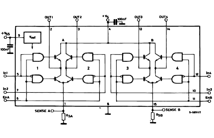
Earlier I wrote about controlling pairs of contacts. In the L298 system, our pairs S1-S2 correspond to input IN1, S3-S4 to input IN2 for the first bridge (OUT1, OUT2 output), input IN3 and IN4 are pairs S1-S2 and S3-S4 of the second bridge (output OUT3, OUT4). You remember from what I wrote earlier, when controlling two pairs at the same time, the forbidden state appears - here, in the L298 circuit, such a state will not occur, as you can see in the block diagram of this bridge below.
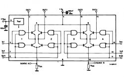
In case of the appearance of identical logic states on IN1-IN2 or IN3-IN4, there will be no short circuit. When a low state appears at both inputs at the outputs at the same time, we will have minuses, while at high states at the inputs at the outputs, there will be pluses, so there will be no short circuit, nor will our motor start. If we want to drive our motor to the right we give "1" to IN1 or IN3 or when we want to drive it to the left we give "1" to IN2 or IN4.
Our bridge allows us to power the motor consuming 2A current, the bridge is able to give us 3A in the "peak".
The L298 system has two inputs which the PCB manufacturer did not use. We are talking about pins 1 and 15 called "Current sensing A" and "Current sensing B", which, when connected in series with properly selected resistors to ground, are used to control the load current.
Below is a short program written in BASCOM, where we can adjust the speed and direction of the motor rotation with the use of four buttons. The speed control only works when the engine is stopped. The program starts with a PWM filling of approx. 49%. Remember that when the PWM frequency is too high, the motor will lose power and that the motor will stop with a higher filling and not only with a filling equal to zero.
Below is a short video of how it actually works.
[movie: 3fe4699d3f] https://filmy.elektroda.pl/83_1528077404.mp4 [/ movie: 3fe4699d3f]
This module can also be used to control a unipolar stepper motor. It is enough to connect the common terminals of the coils together and connect them to ground, and connect the four ends of the coil windings to the OUT1-OUT4 outputs. The ENA and ENB jumpers should be left here because here the speed control is achieved through the delay between the coils and not the PWM control.
Below is a program written in BASCOM where we have two buttons - one allows the engine to move to the right, the other to the left. Each button press takes one sequence - 4 steps. Holding the button will repeat the sequence, i.e. as long as you hold the button, the engine is spinning. Changing the "Waitms 15" time will cause the motor speed to change.
Below is a video of the action.
[movie: 3fe4699d3f] https://filmy.elektroda.pl/68_1528077512.mp4 [/ movie: 3fe4699d3f]
This module can also be used to control a bipolar stepper motor. In the case of controlling stepper motors, the L298 acts as an "amplifier" of the input signal.
This module is quite popular and cheap. You can mock it from Allegro for a shipping price from PLN 15.49 or on Aliexpress for a price from $ 1.28 including shipping.
Module dimensions: 44x44x30mm.
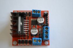
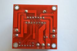
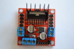
Finally, a few oscillograms.
Output with connected DC motor.
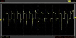
Output without connected DC motor.
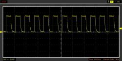
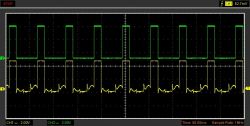
Output (yellow) and input (green) with connected unipolar motor.
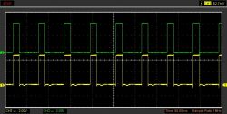
Output (yellow) and input (green) without unipolar motor connected.
The H-bridge is an electrical system that allows you to change the direction of a DC motor by reversing the polarity of the voltage at its output. Such a bridge can be made of e.g. relays, transistors or a ready-made integrated circuit can be used.
The name comes from the graphic representation of the layout. Such a bridge is made of 4 contacts which are switched in pairs.
Below is a graphic representation of the H.

The contact S1 and S4 form one pair and the contact S2 and S3 form the second pair. Switching on one pair of S1-S4 results in a positive potential on the left pole of the motor and negative on the right pole. Switching on the second pair, S2-S3, causes the reversal of this polarity, which changes the direction of the current flow and, as a result, the direction of rotation of the motor.
Building an H bridge on relays is quite simple and does not require complicated control. However, this solution has some disadvantages - contact resistance, contact life and its number of contacts. By adding a transistor to this system, we gain an additional function thanks to which we can regulate the speed of the motor powered from such a bridge.
You can also use bipolar transistors or MOSfets to build bridges.
With the above-mentioned bridges, it should be noted that during their control, a certain state appears which can be said to be forbidden, i.e. we cannot control all our contacts at the same time, we can only control pairs S1-S4 or S2-S3, otherwise the system will create short circuit.
H bridges are used quite often, for example, in the construction of sumo, micromouse or linefolower robots, they can also be found in power steering systems in cars.
A bit of theory behind us so we already know what it is and what it is for. Now we can take care of our layout on the subject. The L298 is a double H-bridge in a Mulitwatt 15 housing. The word "double" here means that in one housing we have two separate bridges, which will allow us to operate two DC motors.
The module discussed here is a ready-to-use system where, after connecting the power supply and connecting the engine, we can start playing with the engine.
Below is a photo and description of the connectors and outputs of this module.

Below is a diagram of the module.

As you can see from the photos and the diagram, we have two power supplies here - one to power the motor, the other to power the bridge logic. The manufacturer of the board stated that the logic power supply is 5VDC and the motors are 12VDC. Looking at the documentation, we can find that the logic power supply can be 4.5-7VDC and the power supply for motors up to 46VDC. However, looking at the board, we can see that the capacitors used here are for voltage up to 35V, so we should not exceed their voltage.
On the board we can also find a 78M05 stabilizer in the TO-252 housing, the supply voltage of which is in the range 7-35V, which means that if we want to supply the motors with a voltage lower than 7V or higher than 35V (but here we are limited by capacitors), it would belong to the ARK connector connect 5V and remove the power jumper which supplies power from the stabilizer to L298. If we are going to use motor power supply in the 7-35V range, we can only supply the motors to the ARK connector and leave the jumper on. In addition, the board has a LED indicating that the voltage is appliedon the logic of the system and diodes protecting against overvoltages when the motor winding is disconnected. On the PCB, we have two more ARK connectors for connecting two motors and a goldpin strip with descriptions: ENA, IN1, IN2, IN3, IN4, ENB. These are the inputs for controlling our bridge. ENA enables operation of the OUT1, OUT2 outputs, and ENB enables the OUT3, OUT4 outputs. The EN input can be used in two ways - the first is to leave the jumpers in their places, where for control it is enough to give the high states to the IN inputs or remove the jumpers and to the lower row of goldpins in place of EN, give the PWM signal thanks to which we will be able to regulate the motor speed or obtain soft start and engine stop.
Earlier I wrote about controlling pairs of contacts. In the L298 system, our pairs S1-S2 correspond to input IN1, S3-S4 to input IN2 for the first bridge (OUT1, OUT2 output), input IN3 and IN4 are pairs S1-S2 and S3-S4 of the second bridge (output OUT3, OUT4). You remember from what I wrote earlier, when controlling two pairs at the same time, the forbidden state appears - here, in the L298 circuit, such a state will not occur, as you can see in the block diagram of this bridge below.

In case of the appearance of identical logic states on IN1-IN2 or IN3-IN4, there will be no short circuit. When a low state appears at both inputs at the outputs at the same time, we will have minuses, while at high states at the inputs at the outputs, there will be pluses, so there will be no short circuit, nor will our motor start. If we want to drive our motor to the right we give "1" to IN1 or IN3 or when we want to drive it to the left we give "1" to IN2 or IN4.
Our bridge allows us to power the motor consuming 2A current, the bridge is able to give us 3A in the "peak".
The L298 system has two inputs which the PCB manufacturer did not use. We are talking about pins 1 and 15 called "Current sensing A" and "Current sensing B", which, when connected in series with properly selected resistors to ground, are used to control the load current.
Below is a short program written in BASCOM, where we can adjust the speed and direction of the motor rotation with the use of four buttons. The speed control only works when the engine is stopped. The program starts with a PWM filling of approx. 49%. Remember that when the PWM frequency is too high, the motor will lose power and that the motor will stop with a higher filling and not only with a filling equal to zero.
Code: VB.net
Below is a short video of how it actually works.
[movie: 3fe4699d3f] https://filmy.elektroda.pl/83_1528077404.mp4 [/ movie: 3fe4699d3f]
This module can also be used to control a unipolar stepper motor. It is enough to connect the common terminals of the coils together and connect them to ground, and connect the four ends of the coil windings to the OUT1-OUT4 outputs. The ENA and ENB jumpers should be left here because here the speed control is achieved through the delay between the coils and not the PWM control.
Below is a program written in BASCOM where we have two buttons - one allows the engine to move to the right, the other to the left. Each button press takes one sequence - 4 steps. Holding the button will repeat the sequence, i.e. as long as you hold the button, the engine is spinning. Changing the "Waitms 15" time will cause the motor speed to change.
Code: VB.net
Below is a video of the action.
[movie: 3fe4699d3f] https://filmy.elektroda.pl/68_1528077512.mp4 [/ movie: 3fe4699d3f]
This module can also be used to control a bipolar stepper motor. In the case of controlling stepper motors, the L298 acts as an "amplifier" of the input signal.
This module is quite popular and cheap. You can mock it from Allegro for a shipping price from PLN 15.49 or on Aliexpress for a price from $ 1.28 including shipping.
Module dimensions: 44x44x30mm.


Finally, a few oscillograms.
Output with connected DC motor.

Output without connected DC motor.

Output (yellow) and input (green) with connected unipolar motor.

Output (yellow) and input (green) without unipolar motor connected.

Cool? Ranking DIY


