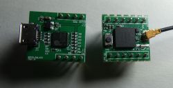
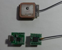
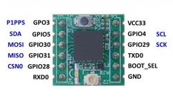
In the offer NavSpark Arduino compatible modules are available, based on a system that integrates a microcontroller and a GPS receiver. It is possible to order a free sample of NavSpark mini with the attached USB UART converter module NavSpark mini + USB adapter or a set of 6 NavSpark mini for $ 36. The module with dimensions 17x17mm does not have a built-in GPS antenna, connect the external antenna to the socket on the board. Outside the module navspark-mini boards with more pins are available, compatible with the Arduino dedicated to GPS, GPS / GLONAS, GPS / BEIDOU . The mini version of the module has been tested with an antenna GPS / GLONAS . According to the manufacturer's description, the module is based on a 32b microcontroller with 1MB of flash memory and 212kB RAM, an FPU (IEEE-754) and a GPS receiver. The LEON3 Sparc-V8 microcontroller clocked at 100MHz, 1x UART, 1x SPI and 1xI2C (shared with GPIO), and 1PPS signal (+/- 10ns) are available on the mini board.
For the version compatible with Arduino are available examples . The mini version is not compatible with all examples, due to, among others, fewer pins and lack UART2 . NavSpark mini can be used without programming as a GPS receiver that sends information via UART. We can check the operation of the module with the software Windows GNSS Viewer . The program allows you to update the firmware, as well as configure the module (e.g. change the UART settings to 115200 to communicate with Arduino).
Including material about GPS NEO-6M you will find a description of the sentence of the NMEA-0183 standard. Using the navspark-mini or NavSpark Arduino module, we can make "our" GPS receiver, which will send data in the format we choose (e.g. NMEA sends coordinates where seconds are written in "decimal" form, we can change the format to minutes and seconds or any other). We can do much more, react to specific circumstances, or e.g. connect the SD card to the SPI interface and record data from the GPS module.
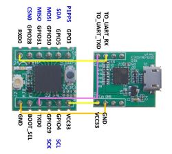
According to the description http://www.navspark.com.tw/tutorial-1 we connect the USB UART converter board with the navspark-mini board.
The converter is based on PL2303 in WIN10 should install automatically, drivers are also available here: http: // www.navspark.com.tw / downloads / The device, when powered from USB, consumes ~ 90mA.
In the Arduino environment, select File-> Preferences and add the line:
http://navspark.mybigcommerce.com/content/package_navspark_index.json
in the Additional URLs to the tile manager field.
Choose: tools-> tile-> tile manager
we search and install "navspark".
Then select: Tools-> Board-> NavSpark mini and Processor Leon3 with GNSS library, select the correct COM port.
Sample codes can be found here: http://www.navspark.com.tw/downloads
Let's try to use NavSpark mini to run a simple device that saves subsequent GPS data on the SD card.
Based on the example of demo_how_to_extract_gps_info, we can save information from GPS to a connected SD card. The device works with a voltage of 3.3V, so the board with a microSD slot does not need a stabilizer and voltage level converter.
We connect the SD card with the module:
DI MISO GPIO31
SCLK

For the version compatible with Arduino are available examples . The mini version is not compatible with all examples, due to, among others, fewer pins and lack UART2 . NavSpark mini can be used without programming as a GPS receiver that sends information via UART. We can check the operation of the module with the software Windows GNSS Viewer . The program allows you to update the firmware, as well as configure the module (e.g. change the UART settings to 115200 to communicate with Arduino).
Including material about GPS NEO-6M you will find a description of the sentence of the NMEA-0183 standard. Using the navspark-mini or NavSpark Arduino module, we can make "our" GPS receiver, which will send data in the format we choose (e.g. NMEA sends coordinates where seconds are written in "decimal" form, we can change the format to minutes and seconds or any other). We can do much more, react to specific circumstances, or e.g. connect the SD card to the SPI interface and record data from the GPS module.

According to the description http://www.navspark.com.tw/tutorial-1 we connect the USB UART converter board with the navspark-mini board.
The converter is based on PL2303 in WIN10 should install automatically, drivers are also available here: http: // www.navspark.com.tw / downloads / The device, when powered from USB, consumes ~ 90mA.

In the Arduino environment, select File-> Preferences and add the line:
http://navspark.mybigcommerce.com/content/package_navspark_index.json
in the Additional URLs to the tile manager field.
Choose: tools-> tile-> tile manager
we search and install "navspark".
Then select: Tools-> Board-> NavSpark mini and Processor Leon3 with GNSS library, select the correct COM port.
Sample codes can be found here: http://www.navspark.com.tw/downloads
Let's try to use NavSpark mini to run a simple device that saves subsequent GPS data on the SD card.
Based on the example of demo_how_to_extract_gps_info, we can save information from GPS to a connected SD card. The device works with a voltage of 3.3V, so the board with a microSD slot does not need a stabilizer and voltage level converter.
We connect the SD card with the module:
DI MISO GPIO31
SCLK
Cool? Ranking DIY


