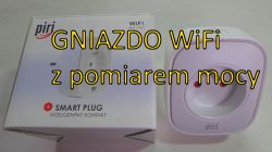
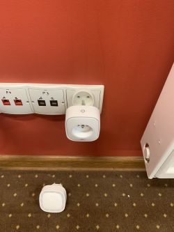
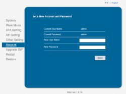
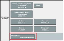
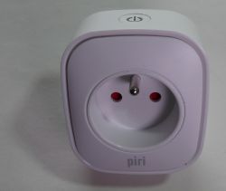
Piri made it available to us for testing remote controlled socket WiFi 2.4GHz to measure the power consumed by the connected device. In the video you will find the results of the socket tests, we will also take a look inside the housing.
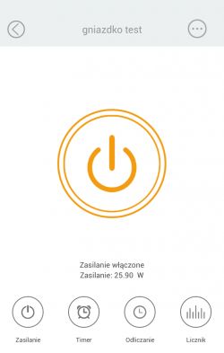
The control of switching on the connected device and the reading of power consumption is possible thanks to the smartphone application: Piri smart home .
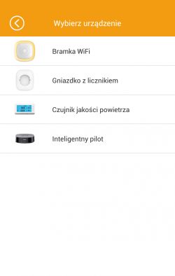
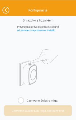
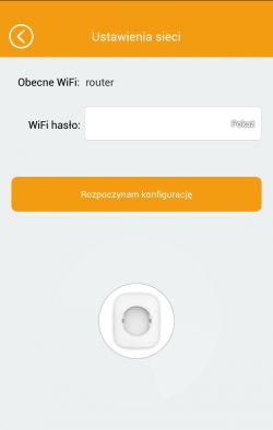
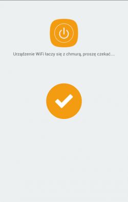
The socket is compact and ready to use out of the box, it can switch powers up to 3kW, while the application guides you through the process of connecting to your home WiFi network. We set up an account in the operator's cloud in the application using the e-mail address we have. We put the device into pairing mode by holding the button for 5s, then the LED will start flashing quickly. In order for the application to connect the socket to our WiFi network, broadcasting of the network SSID should be started on the AP, and the socket's MAC must be on the list of devices allowed to connect to our WiFi AP.
DEVICE CONTROLS
We can control the device connected to the socket:
- manually with a button on the socket housing,
- from anywhere in the world where we have access to the Internet, using the application on a smartphone,
-using schedules of switching on and off, as well as a timer configured by the application.
The schedules set in the application are launched in the operator's cloud and the socket will be switched regardless of whether our smartphone and application have an internet connection. The condition for remote control of the socket is its continuous connection to the Internet.
OPERATION AND CONSTRUCTION OF THE NEST:
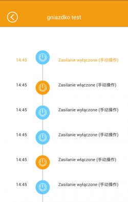
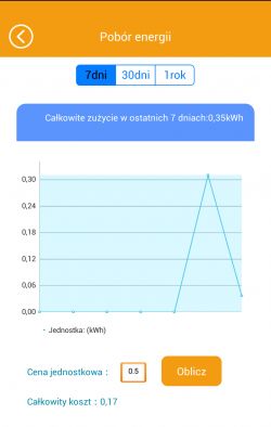
The application is convenient to use, but minor adjustments would be needed, e.g. polonization of messages in the operation log and increasing the resolution of measurement points on the time axis.
It is worth taking a look at the Piri YT channel, you will find there materials about both the WiFi socket and, for example, a wireless camera:
https://www.youtube.com/watch?v=q1VYP0bVcg8
The socket, when powered by ~230.8VAC, consumes 3.14mA with the relay off and 6.73mA with WiFi activity, while 9.44mA with the relay on and 11.64mA with WiFi activity.
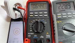
Comparison of the indications of the device with the bulb connected is 158W in the application on the smartphone and 148W from the indications of the connected multimeters.
Connecting the iron gave an indication in the application of 1092W, multimeter indications are 1013W.
Connecting a 1uF capacitor gave an indication of 0W, while the ammeter indicated 73mA way to go! the socket actually indicates active power .
A PF (power factor) measurement would also be useful.
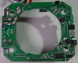
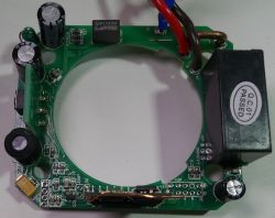
We look inside the socket and the thoughtful compact design immediately catches the eye. It is easy to locate the measuring resistor and the WiFi module.
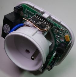
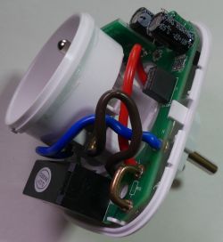
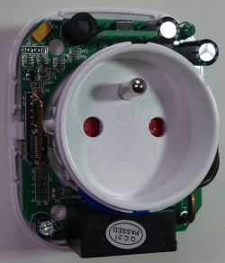
The WiFi module is based on the Mediatek MT5931 chip (802.11n 2.4HGz) and ARM MC101, after a while of searching you can find information about the module in the network: Micro UART To WiFi Module . The WiFi antenna is made in the form of a wire section - there is room for development in the direction of a PCB or ceramic antenna.
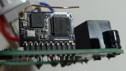
On the board you will find a 250V/16A relay controlling the connected device, a switching power supply based on the LNK306N, the HLW8012 power measurement system and the STM8 8S003FP6 microcontroller. More about the power measurement system can be found, for example, here: HLW8012 .
Where do you see a use for a remote-controlled WiFi socket with power measurement?
Personally, I see an application in the control of electric heating and air conditioning (provided that the air conditioner will start after powering up). Power metering can help you optimize your energy costs, while remote control and scheduling can help you stay in control of your connected device. During an unexpected change in the weather or when plans change, the socket could turn on the heating or air conditioning and prepare the house for our return.
There are days when such a socket would be useful to run an overflow coffee machine in the kitchen, when the alarm clock in the bedroom does not let us sleep
- of course, you should properly "arm" such a coffee machine the day before ...
An interesting development of the design would be the possibility of indicating in the application, apart from active power/energy, other parameters, e.g. power factor, mains voltage, current consumed by the receiver, counting inductive and capacitive reactive energy. Even if the values were approximate as in simple energy meters: measurement of active, reactive and apparent power that would be an interesting feature. Perhaps such functionality can be added by changing the firmware and by expanding the application?
We tested before wireless outdoor WiFi camera also shared by Piri.
[ADVERTISING COLLABORATION]
The control of switching on the connected device and the reading of power consumption is possible thanks to the smartphone application: Piri smart home .
The socket is compact and ready to use out of the box, it can switch powers up to 3kW, while the application guides you through the process of connecting to your home WiFi network. We set up an account in the operator's cloud in the application using the e-mail address we have. We put the device into pairing mode by holding the button for 5s, then the LED will start flashing quickly. In order for the application to connect the socket to our WiFi network, broadcasting of the network SSID should be started on the AP, and the socket's MAC must be on the list of devices allowed to connect to our WiFi AP.


DEVICE CONTROLS
We can control the device connected to the socket:
- manually with a button on the socket housing,
- from anywhere in the world where we have access to the Internet, using the application on a smartphone,
-using schedules of switching on and off, as well as a timer configured by the application.
The schedules set in the application are launched in the operator's cloud and the socket will be switched regardless of whether our smartphone and application have an internet connection. The condition for remote control of the socket is its continuous connection to the Internet.
OPERATION AND CONSTRUCTION OF THE NEST:
The application is convenient to use, but minor adjustments would be needed, e.g. polonization of messages in the operation log and increasing the resolution of measurement points on the time axis.


It is worth taking a look at the Piri YT channel, you will find there materials about both the WiFi socket and, for example, a wireless camera:
https://www.youtube.com/watch?v=q1VYP0bVcg8
The socket, when powered by ~230.8VAC, consumes 3.14mA with the relay off and 6.73mA with WiFi activity, while 9.44mA with the relay on and 11.64mA with WiFi activity.
Comparison of the indications of the device with the bulb connected is 158W in the application on the smartphone and 148W from the indications of the connected multimeters.
Connecting the iron gave an indication in the application of 1092W, multimeter indications are 1013W.
Connecting a 1uF capacitor gave an indication of 0W, while the ammeter indicated 73mA way to go! the socket actually indicates active power .
A PF (power factor) measurement would also be useful.

We look inside the socket and the thoughtful compact design immediately catches the eye. It is easy to locate the measuring resistor and the WiFi module.


The WiFi module is based on the Mediatek MT5931 chip (802.11n 2.4HGz) and ARM MC101, after a while of searching you can find information about the module in the network: Micro UART To WiFi Module . The WiFi antenna is made in the form of a wire section - there is room for development in the direction of a PCB or ceramic antenna.

On the board you will find a 250V/16A relay controlling the connected device, a switching power supply based on the LNK306N, the HLW8012 power measurement system and the STM8 8S003FP6 microcontroller. More about the power measurement system can be found, for example, here: HLW8012 .


Where do you see a use for a remote-controlled WiFi socket with power measurement?
Personally, I see an application in the control of electric heating and air conditioning (provided that the air conditioner will start after powering up). Power metering can help you optimize your energy costs, while remote control and scheduling can help you stay in control of your connected device. During an unexpected change in the weather or when plans change, the socket could turn on the heating or air conditioning and prepare the house for our return.
There are days when such a socket would be useful to run an overflow coffee machine in the kitchen, when the alarm clock in the bedroom does not let us sleep
- of course, you should properly "arm" such a coffee machine the day before ...
An interesting development of the design would be the possibility of indicating in the application, apart from active power/energy, other parameters, e.g. power factor, mains voltage, current consumed by the receiver, counting inductive and capacitive reactive energy. Even if the values were approximate as in simple energy meters: measurement of active, reactive and apparent power that would be an interesting feature. Perhaps such functionality can be added by changing the firmware and by expanding the application?

We tested before wireless outdoor WiFi camera also shared by Piri.
[ADVERTISING COLLABORATION]
Cool? Ranking DIY


