 .
.
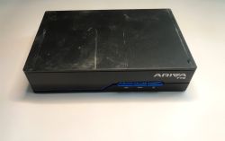
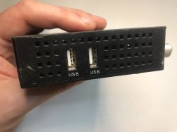
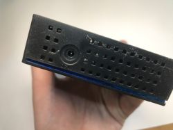
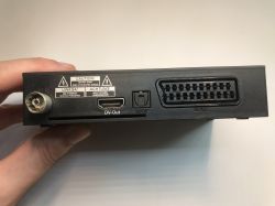
I'd like to invite you to a brief analysis of another piece of television equipment. This time I received a slightly newer, but again decomposed device. Ariva T75 without power supply and remote control - this decoder has already been shown on our forum . From the outside, the whole thing appears quite minimalist, but what else besides HDMI does a typical user need?
 .
.
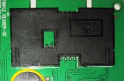
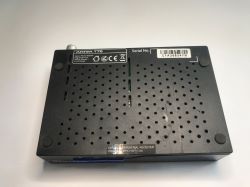
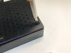
Virtually no one uses such USB ports for storage devices in my area. Time to look inside - the screws are under the feet:
 .
.
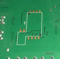
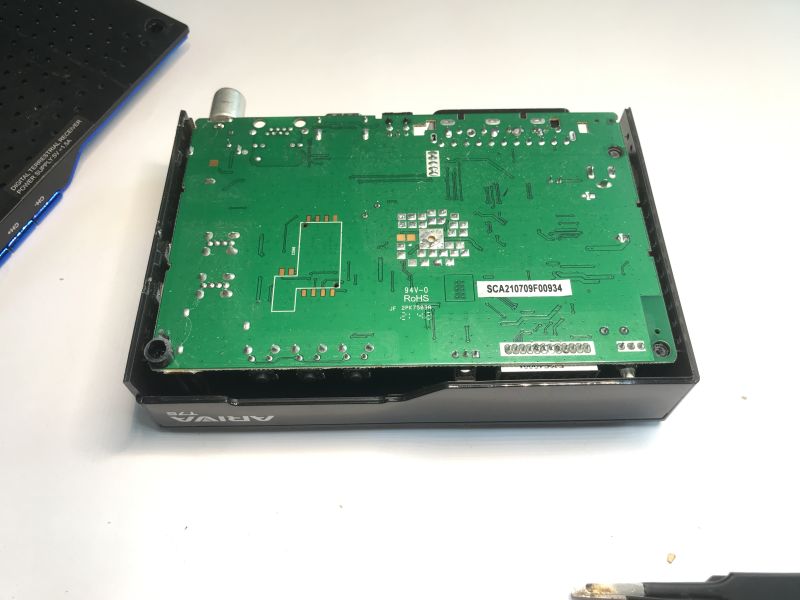
The PCB is one - the power supply is external. I was interested in this footprint of some module on the bottom, anyone know what it is from?
 .
.
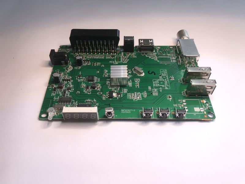
The PCB designation is HMT22301T1-D 20210425 Four year old hardware. Apart from this you can already see the standard sections:
- inverters (voltages for memory and processor)
- processor and next to it the Flash memory
- display, buttons and their controller, probably with SPI or I2C interface
- RF tuner
 .
.
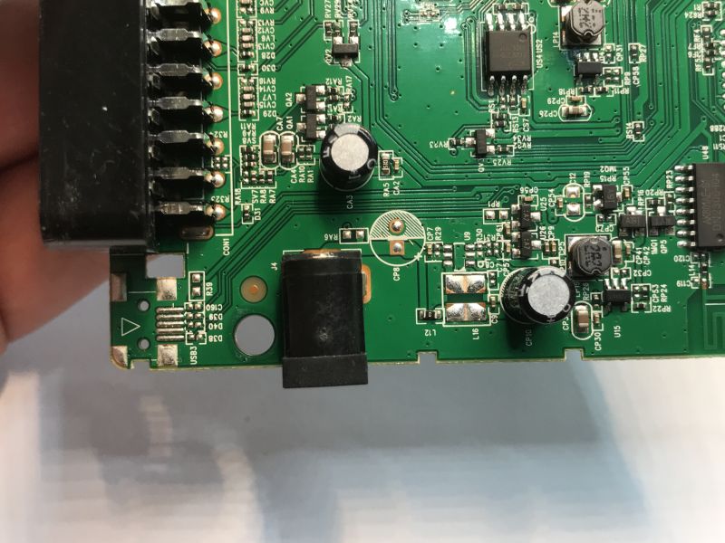
In the power section I see traces of an option with a Micro USB connector. Interesting that there is no reverse polarity protection diode, in older equipment I sometimes see it.
 .
.
With the display it is fairly typical. The controller is an FD650B. From what I recall it is the same as the HD2015, so I have already discussed it:
We are running the HD2015 display/button controller after reverse engineering, comparison with TM1637itd .
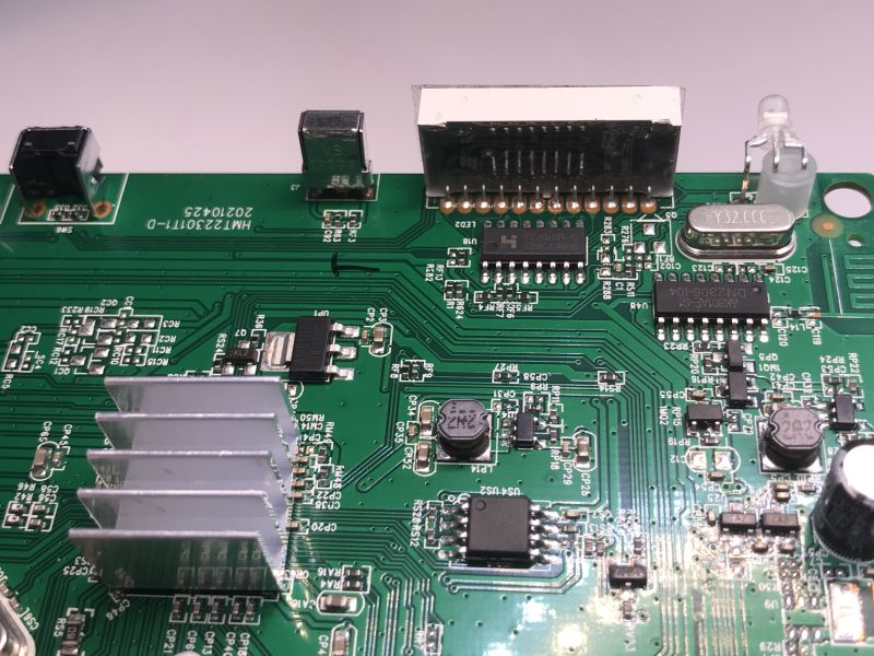
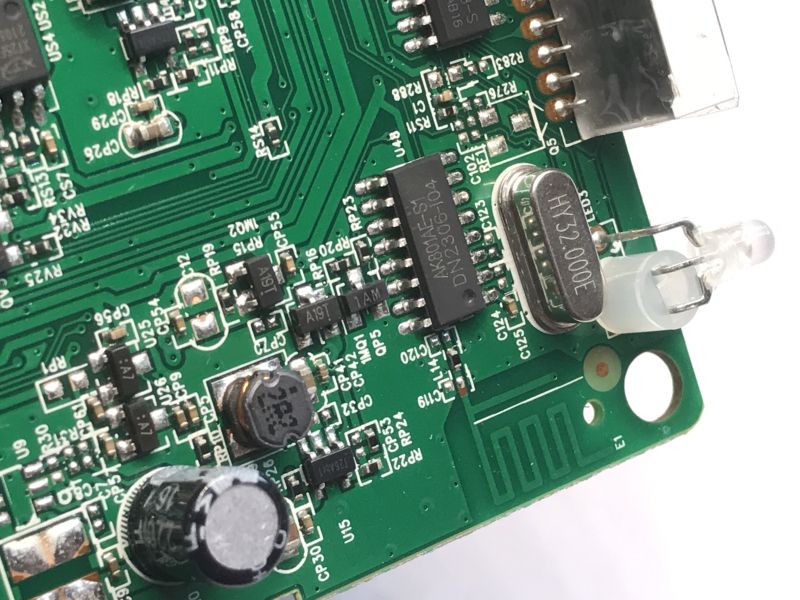
Next to it is more interesting - an AK801AE-S1 DN2306-104 with an antenna. It looks like an RF circuit. I haven't seen this one before.
 .
.
I didn't have to look long for the explanation to this puzzle - it's a Bluetooth chip:
 .
.
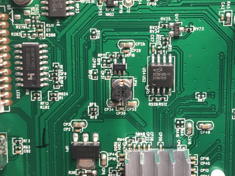
Next we have the aforementioned Flash memory, here as much as 4MB. This could come in handy and after scrapping the tuner:
Additional Flash memory for measurements for free? Communication protocol, write, read, erase .
 .
.
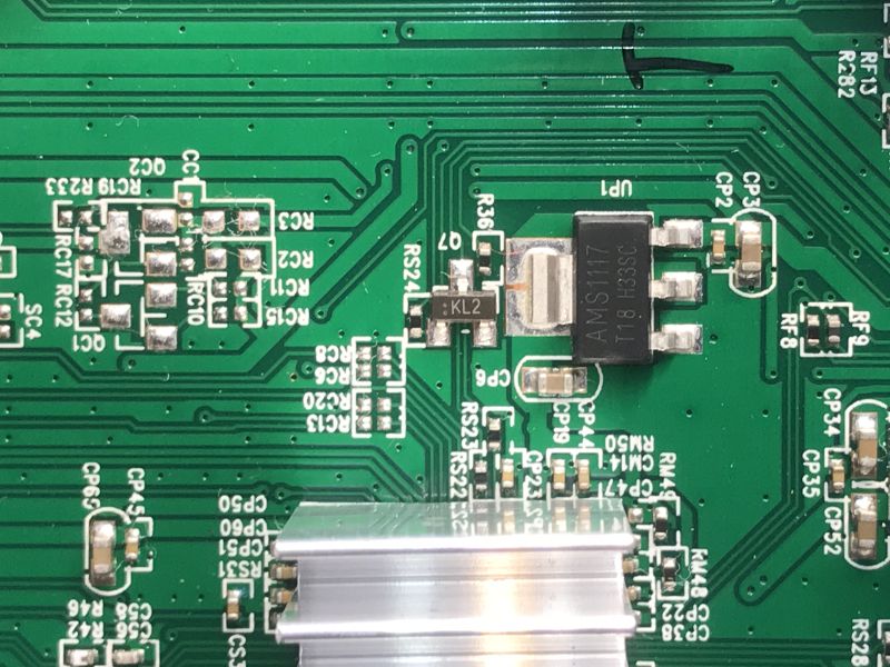
Next up is an element I often see in tuners like this, but it always puzzles me - if we have step down converters, why the extra 1.8V LDO AMS1117?
 .
.
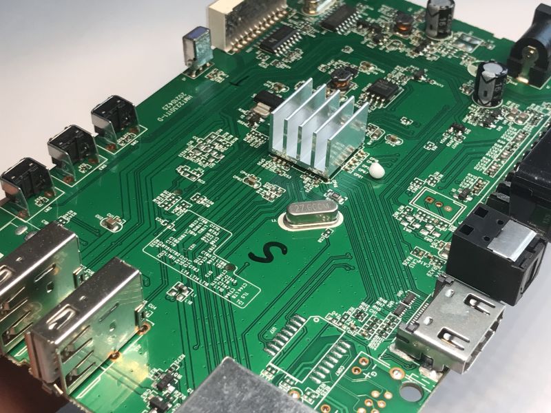
A view of the board - who recognises the CON7 connector? You can also see a potential three-pin connector on the UART in the background.
 .
.
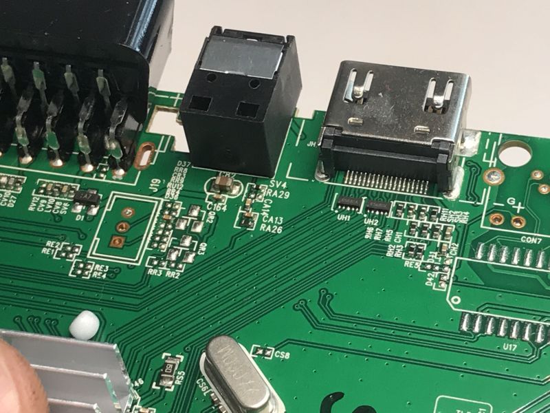
That CON7 looks like an Ethernet connector to me, those LEDs give that away too, and U17 looks like a signal transformer.
HDMI is only connected to the CPU via the components marked UH - probably some sort of filters.
 .
.
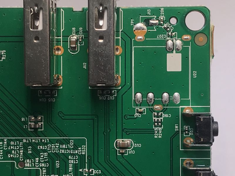
There is one interesting spot left:
 .
.
Here, in turn, was probably meant to be a WiFi module - probably like the one in my colleague's topic:
Interior and quick repair of the LTC LXHD203 DVB-T2 decoder .
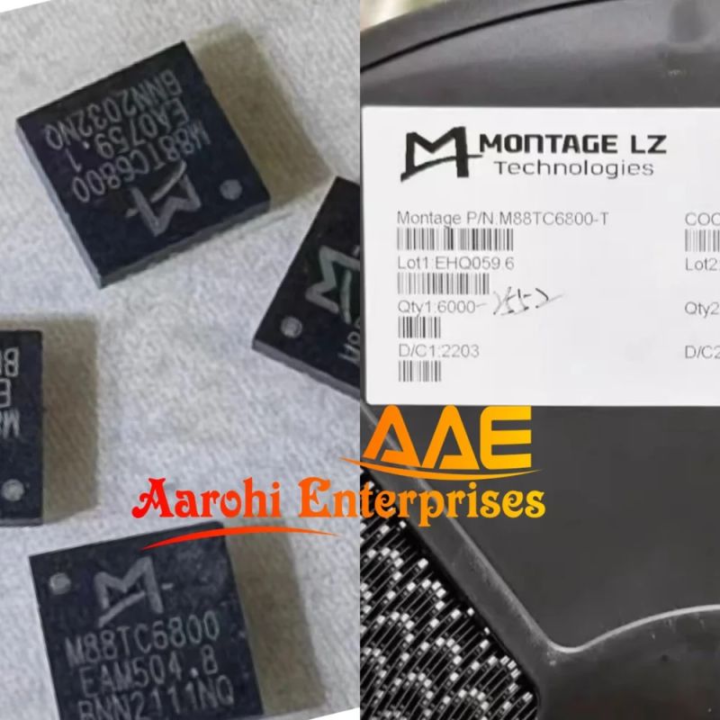
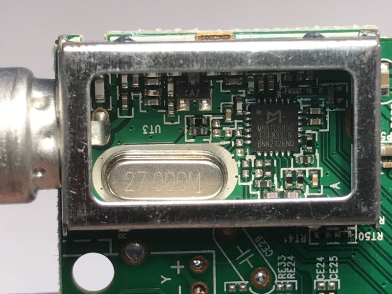
The signal reception is implemented here on, as far as I can see, an M88TC68000:
 .
.
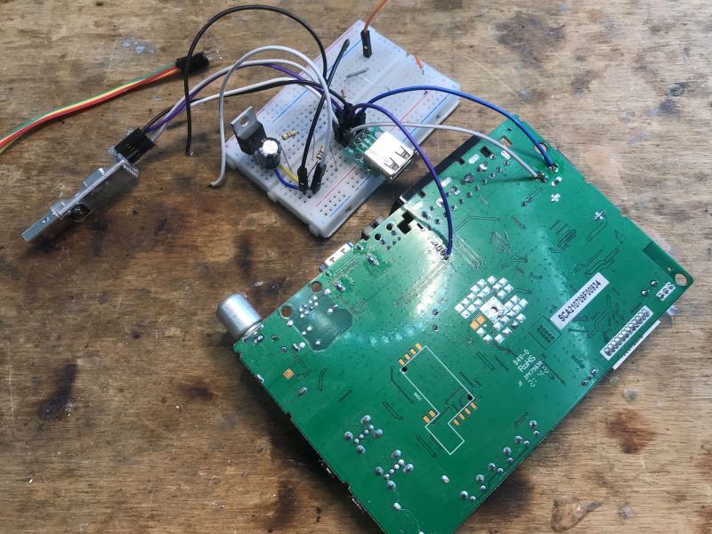
Finally, I tried tapping the UART, but the device is silent:
 .
.
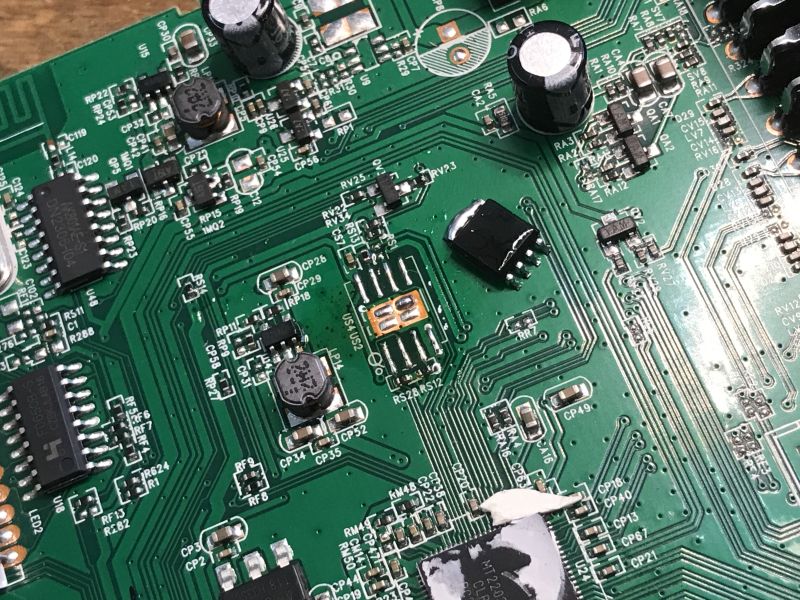
I also dumped the device memory using the CH341 programmer:
 .
.
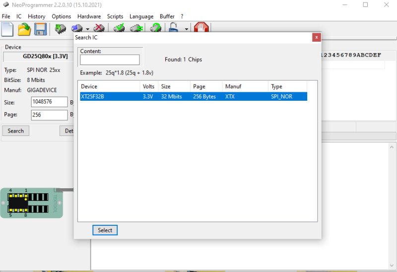
I found interesting messages in my memory - for example "Error cannot boot from media", or "com_bootloader". The firmware was compiled on 21 January 2021.
A copy of the firmware:
https://github.com/openshwprojects/FlashDumps/commit/7fe724b994f5305930d48bb1606fd2d22eec8c30
Feel free to download and experiment - who will find more information in this dump?
In summary , this was slightly newer hardware than I usually show. Again, it came to me without a remote control or power supply, so I don't know what I'm going to do with it. The display from inside would be easy to run with an Arduino or similar microcontroller, and the memory could be useful for DIY too. Of the unusual circuits inside, there was a Bluetooth transceiver and a place for a WiFi module - I didn't see this in older models. I still tried to pick up some UART communication from the board shown, but the port was unfortunately silent. I may yet return to this device.
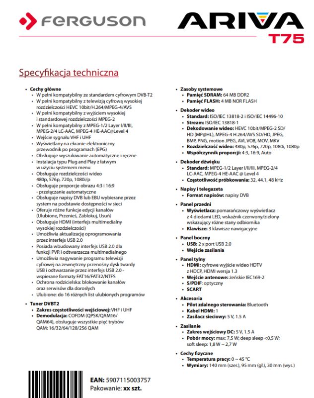
PS: Device specification from the topic:
 .
.
Cool? Ranking DIY Helpful post? Buy me a coffee.


