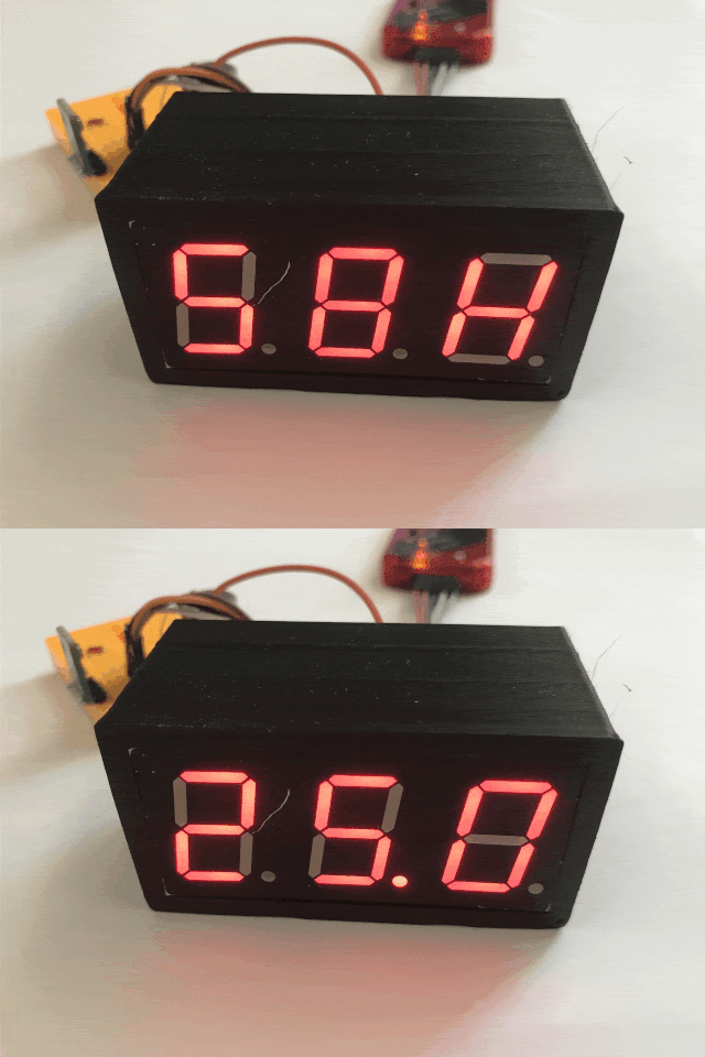
 .
.
I invite you to the second part of the adventure with a thermometer/hygrometer built from 0 based on a PIC18F2550, parts from a drawer and programmed in the SDCC compiler - without external libraries. In this part I will run the ADC, i.e. the analogue-to-digital converter, and realise based on it the brightness control of the display so that at night the segments do not shine too brightly unnecessarily. In addition, I will already start working on the housing here.
In the previous part, I started a 7-segment display with 3 digits based on multiplexing from a timer interrupt on the PIC, and then implemented a simple I2C support in software to take measurements from the AHT20:
Termometer/hygrometer on PIC18F and AHT20 step by step - DIY from scratch - part 1 .
Here I will try to continue and improve this project.
Here we go!
Minor tweaks .
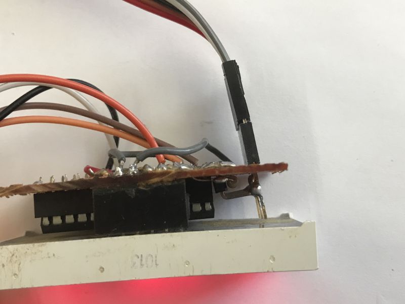
I started with some minor tweaks. The first thing I did was to reduce the resistor values, as the display was too dark though. Then I moved the ICSP connector from the programmer so that the whole thing protruded backwards, rather than to the side - this was with the case in mind:
 .
.
Running the ADC .
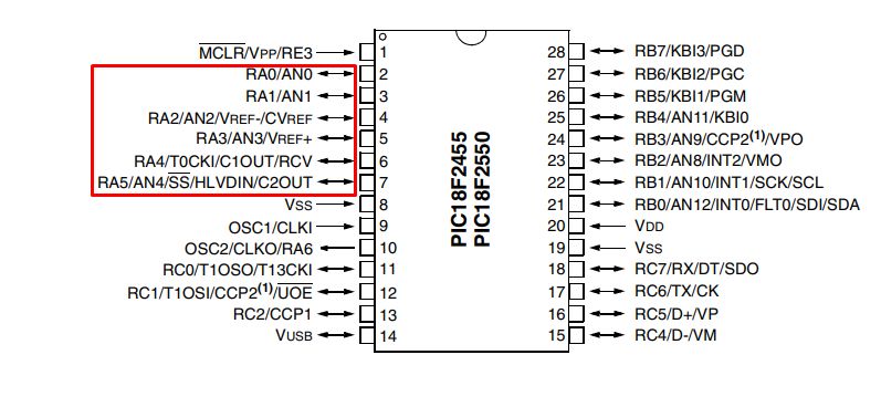
The next step was to run the ADC. I decided to use the A port pins as I already have segments on B:
 .
.
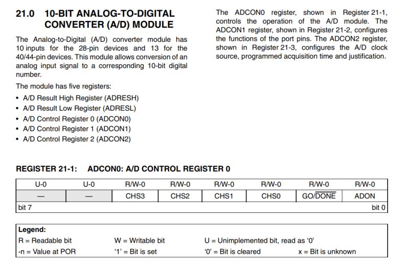
The PIC18F2550 has a 10-bit ADC. We read a 10-bit value from it, that is, in the range 0-1023. The results of the reading are in ADRESH and ADRESL, and it is configured in the ADCON0, ADCON1, ADCON2 registers:
 .
.
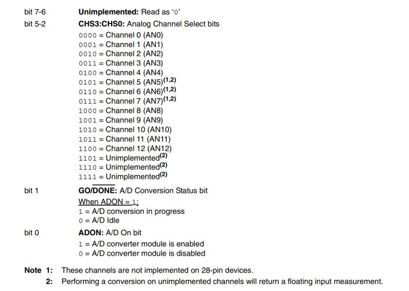
In ADCON0 we enable ADC and select the current channel, you can also check there if the reading has been completed:
 .
.
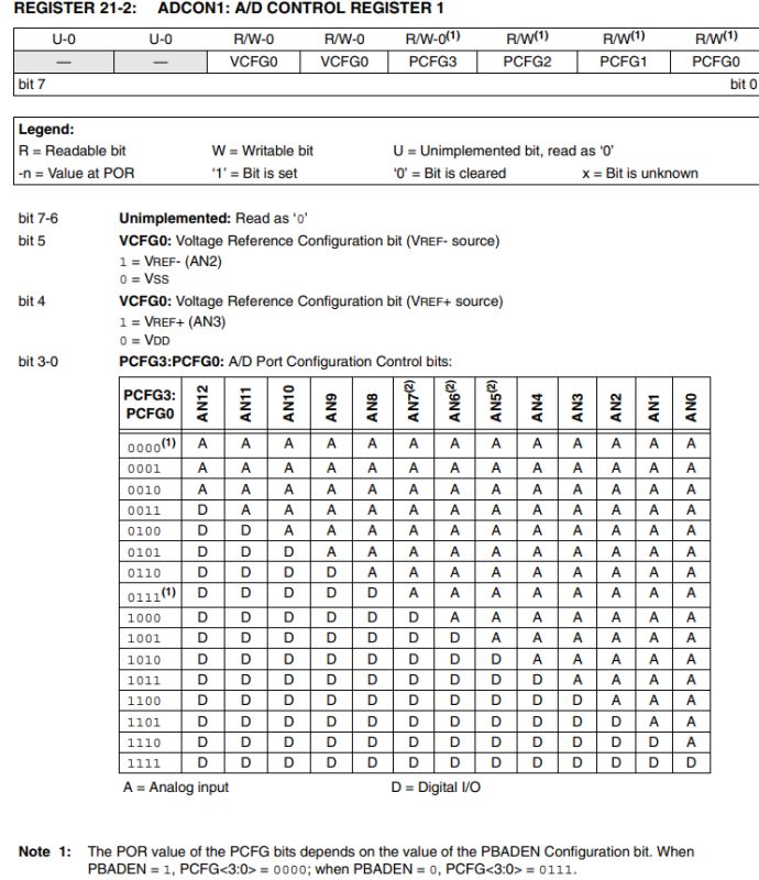
In ADCON1 we select the reference voltages and which AN pins are digital and which are analogue:
 .
.
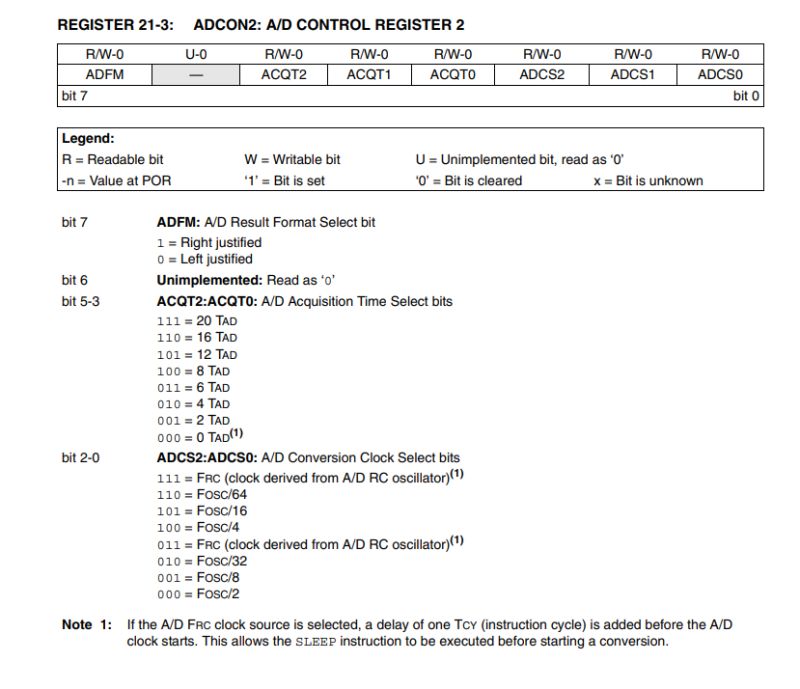
In ADCON2 we set the conversion time and clock, as well as the format of the result:
 .
.
At this stage I can already see one small problem. In the project I used AN0 and AN1 as digital pins for I2C, and I don't want to re-solder the wires. However, from the PCFG3:P CFG0 table, it appears that it is not possible to set AN0 and AN1 to digital mode and, for example, AN2 to analogue mode. I will have to change the ADCON1 value after conversion so that I can use I2C again.
Ok, now it's time to write the values into the code:
Code: C / C++
Now it's time for the reading itself. The conversions are triggered by the GO pin, the microcontroller itself turns it off when the readout is completed. Ostensibly you could do this in an interrupt, or check this pin from time to time, but for the moment let it be a blocking solution. Finally, I combine the two 8-bit words so that I get a 10-bit result:
Code: C / C++
A value in the range 0-1023 can be difficult to process, for convenience I will still convert it to a voltage:
Code: C / C++
Now this needs to be tested. From a software angle, just use our display:
Code: C / C++
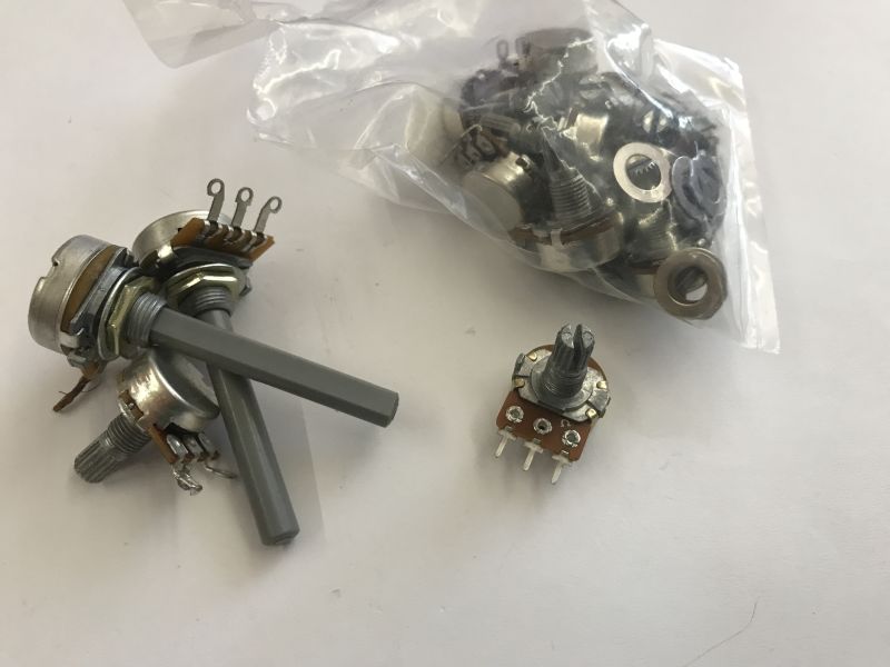
Hardware-wise, it's no more difficult - just apply a voltage from 0 to 5V to the pin of my choice, a potentiometer will do. Such a potentiometer has a tapping inside and is a voltage divider. I connected it between VDD and GND and the tapping to the PIC's leg.
 .
.
Done:
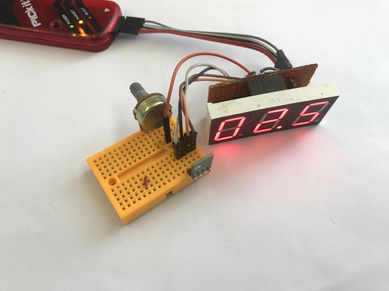 .
.
Time to check the operation:
Display brightness control .
The display at night does not need to be too bright to be seen, and should not even shine too brightly. This makes it uncomfortable, tires the eyesight and is disturbing. During the day, on the other hand, it is difficult to see the barely smouldering characters in good light. For this reason, it is worth trying to adjust their brightness level dynamically.
A photoresistor can help with this - its resistance changes with the light level. I have one myself dating back to a very old time, anyone know what device it might be from?
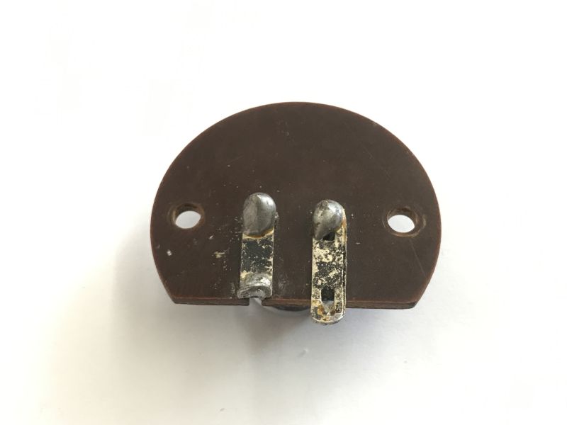 .
.
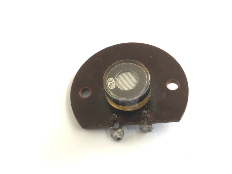 .
.
I also had newer ones, but they were lost somewhere during the refurbishment.
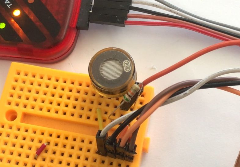
I removed the potentiometer and replaced it with a photoresistor and a regular resistor. I selected the ordinary resistor so that the different light levels covered almost the entire ADC range nicely.
 .
.
In the end it came out that 0V on the ADC was a very dark environment, 3.8V was a typical bright room, and 5V was a torch light beam directed at the sensor.
The next step is to implement this as brightness levels. At this point we have one timer, and each call to it sets another digit:
Code: C / C++
However, this can be exploited and the assumption changed - let's say there will be 8 brightness levels and the timer will call itself those 8 times for each digit and check the current call index against the brightness setting to either light or extinguish the digit based on that. The longer the digit is off, the lower the brightness level.
Code: C / C++
Except that now all the digits change 8 times slower - for this reason I also changed the timer prescaler so that the interrupt is called more often enough:
Code: C / C++
The result in the video - the program below also displays the light level itself as a numerical value (from 0 to 7):
I guess I still need to refresh more often, because there is a flashing on the camera, although with the naked eye I don't feel it at all.
Time to restore the temperature and humidity display:
Code: C / C++
Now the brightness level reacts much slower, it's hard to even show this nicely in the video, but it's hardly a problem - night doesn't come in a dozen seconds anyway....
Case concept .
I wanted to make the enclosure using 3D printing. My first idea was to make the enclosure adjacent to the display. I started by sizing the display and preparing a test print:
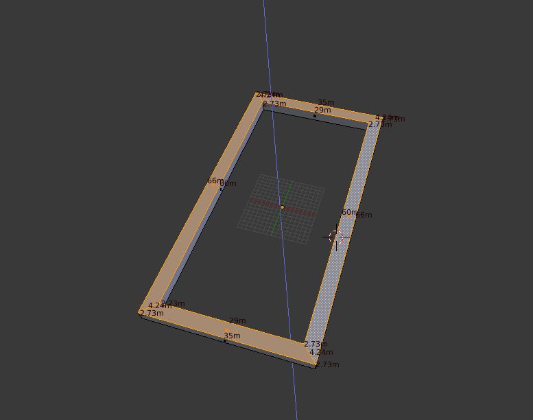 .
.
It went smoothly and the shape overlapped the display just right:
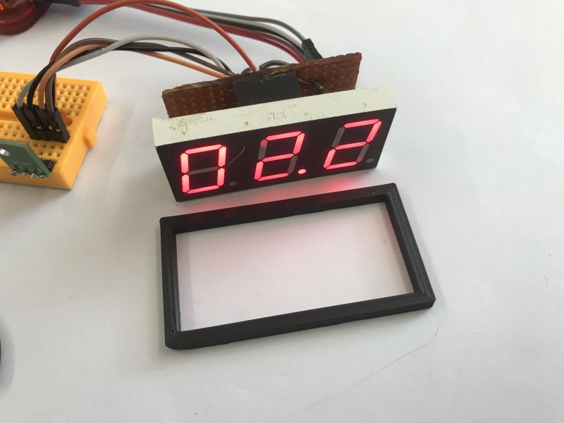 .
.
It was therefore possible to go one step further.
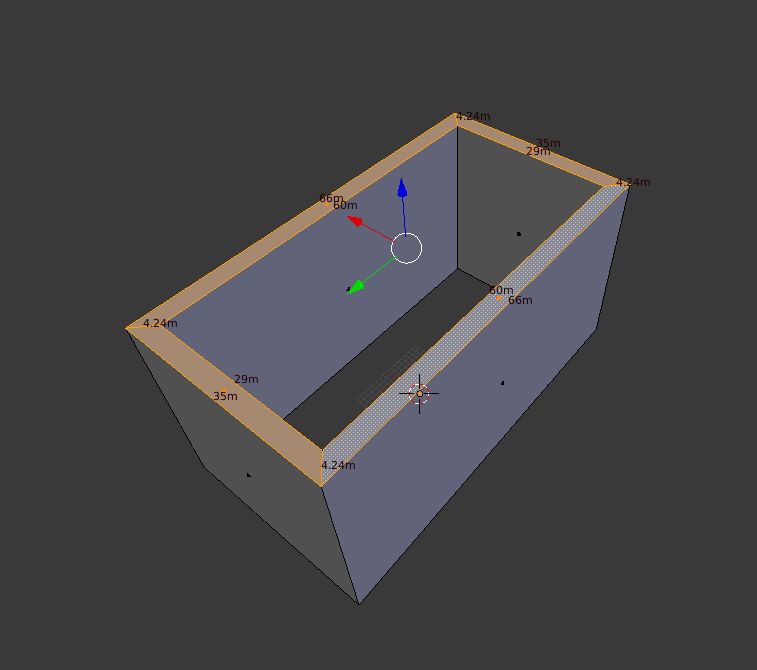 .
.
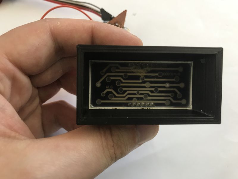
I sanded down the sides of the board so that it did not protrude beyond the display frame and prepared a deeper prototype:
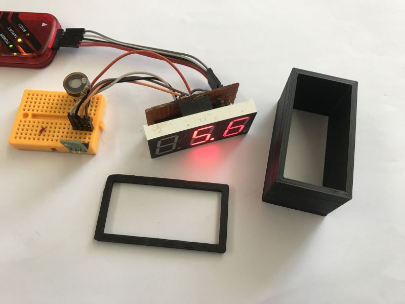 .
.
It fits nicely:
 .
.
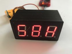
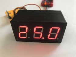
Initial effect:
 .
.
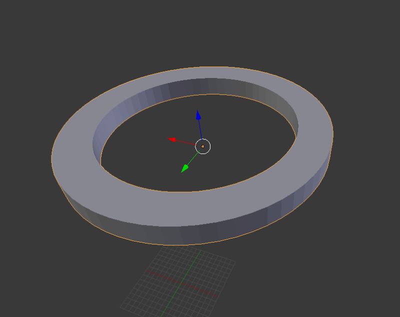
Worse that such an enclosure does not provide for a photoresistor at all... Time to size it up and do something about it. Test print:
 .
.
Fits:
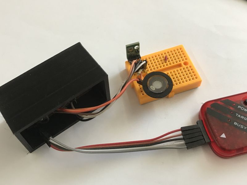 .
.
To test the whole thing:
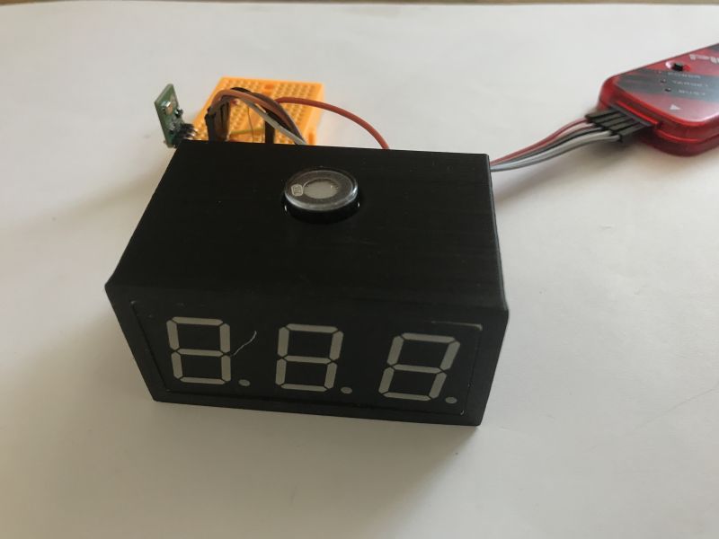 .
.
I'm not sure this is such a good idea....
Code of the current version for reference:
Code: C / C++
Summary of part two .
In this step, I first made the necessary error corrections from the first part, i.e. increased the segment current slightly so that the display was brighter. Then I moved the connector from the ICSP so that it didn't stick out from the side, which blocked me from adding a straight housing.
I then decided to add a brightness control for the display. On the hardware side, there was one problem, because the PIC18F2550 allows you to run the analogue pins "counting from 0", and I had already allocated RA0 and RA1 for I2C, so in the end, not wanting to re-solder the bus, I decided to reconfigure the port every reading. On the software side it went smoothly, I just increased the interrupt frequency and added a simple compare and count into it - from now on there are 8 interrupts per digit, where in each one I check if the current counter has reached a given brightness level and based on that I light or turn off the digit.
Finally, I started experimenting with the casing - I decided on a version adjacent directly to the display, the front of which even matches the overall colour, although these blemishes could use some painting.
However, the photoresistor complicates matters a bit, because at the moment I'm not sure where to put it - my concept of the case doesn't provide for it, and if I put it on top, then placing the device on a shelf will make it partially covered. I need to rethink that.
I plan to do a third part of the presentation where I will add:
- a simple calibration of the readouts via hardware USB from the PIC18F2550 (this doesn't require many external components, no USB to UART converters, etc)
- the final form of the enclosure, this time probably already complete, with a micro or mini USB socket on the back to use an old phone power supply
In addition, I have two more potential improvements to make:
- maybe it would be possible to implement the brightness level control more cleverly, instead of calling the interrupt N times for N available levels, to call it twice and dynamically count the timer overflow values
- it would be good to sort out the peripherals on port A, so that I don't have to change the mode (analog/digital) every now and then, this is due to the limitation of the PIC, this will also make it possible to move the ADC reading to the interrupt, so that it is not blocking (only examine the corresponding bit)
That's it for now, feel free to comment, do you perhaps have any suggestions on how to implement the housing and position of the photoresistor in the final version? Or have you recently done something using the "100% DIY" method, as I tried to do in this topic?
Cool? Ranking DIY Helpful post? Buy me a coffee.


