logo elektroda
logo elektroda
X
logo elektroda

Connecting Whirlpool SMC 654 F / BT / IXL Induction Hob to a Three-Phase Installation

Mastahkilla 13374 10
ADVERTISEMENT
Treść została przetłumaczona polish » english Zobacz oryginalną wersję tematu
  • #1 17524829
    Mastahkilla
    Level 2  
    Hello

    I would like to know how to properly connect the Whirlpool SMC 654 F / BT / IXL induction hob to a three-phase installation. Photo of the terminal box on the board
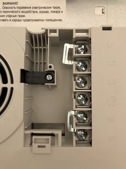
    Connecting Whirlpool SMC 654 F / BT / IXL Induction Hob to a Three-Phase Installation
    Picture of the connection diagram on the hob casing (right under the terminal box).
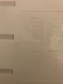
    Connecting Whirlpool SMC 654 F / BT / IXL Induction Hob to a Three-Phase Installation
    Screen of the connection diagram in the user manual.
    Connecting Whirlpool SMC 654 F / BT / IXL Induction Hob to a Three-Phase Installation
    The set also includes a connecting cable
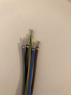
    Connecting Whirlpool SMC 654 F / BT / IXL Induction Hob to a Three-Phase Installation
    A standard 5-core cable (black, brown, gray, blue, yellow-green) comes out of the wall. I checked with a voltage meter:
    blue - black - 230V
    blue - brown - 230V
    blue - gray - 230V
    black - brown - 400V
    black - gray - 400V
    brown - gray - 400V
    blue - yellow-green - 0V
    My guess is that in the terminal box on the board I remove the jumper between L1 and L2.
    I connect the black wire to the L1 terminal on the board
    I connect the brown wire to the L2 terminal on the board
    I connect the yellow-green wire to the protective terminal on the board
    But I have a dilemma further, because I have the impression that the diagrams on the housing and the manual differ a bit. I would be very grateful for your help.

    best regards

    Konrad
  • ADVERTISEMENT
  • Helpful post
    #2 17524839
    Piotr2608

    Level 41  
    You just call an electrician who will install this board for you (of course with permissions)
    I need a stamp in the warranty.
    It is better to spend PLN 100 on a professional than regret that you lost a new album.
  • ADVERTISEMENT
  • #3 17524861
    Mastahkilla
    Level 2  
    Of course, you are right. I will probably do that. However, you can find various professionals (as my friend found out and what I read on the forum), so I prefer to know how it should be connected and check whether the specialist connects the same.
  • #4 17595701
    popek76
    Level 1  
    I have a question, did you manage to connect this disc? I have the same problem. I bought it yesterday and I have slight concerns. I will be grateful for your help
    Peter
  • ADVERTISEMENT
  • #5 17595734
    ta_tar
    Level 41  
    Mastahkilla wrote:
    But I have a dilemma further, because I have the impression that the diagrams on the housing and the manual differ a bit.

    Indicate the differences in the diagram and in the drawing from the housing. Look at the sign, not where it is. The different order in the schematic may be because you have an instruction not exactly from that model. You have the order of the points on the casing and the physical ones correctly.
  • #6 17612042
    Mastahkilla
    Level 2  
    popek76 wrote:
    I have a question, did you manage to connect this disc?

    This is how I connected according to the diagram on the housing and it works OK.
    ta_tar wrote:
    Indicate the differences in the diagram and in the drawing from the housing.
    In the figure on the housing, all three phases are connected, in the figure in the manual, the third phase connector is unconnected, while the gray wire (3rd phase) is connected to the blue wire (neutral). Besides, in the paper manual it looks as if the connected wires are already coming out of the induction.
    ta_tar wrote:
    The different order in the schematic may be because you have an instruction not exactly from that model.
    A paper instruction was attached to the new induction. I also checked the manufacturer's website and for this model it is exactly the same as I had in the set.
  • ADVERTISEMENT
  • #7 17986248
    tobiasz91
    Level 9  
    I have the same problem with this album :) I connected it according to the first diagram from the disc, but when I looked at the manual, I was crazy :) that is, you connected according to the first diagram from the board for 3 phases? Three phases for three terminals, neutral to bridged N and protection?
  • #8 17986255
    mqsak
    Level 2  
    The third phase is not used anyway. The hob works on 2 phases. The third is bridged with the neutral to "increase" the diameter of the conductor. At least that's what a Whirlpool service technician explained to me. I have it so connected and it works. Only the board and the box have to be bridged :)
  • #9 17986488
    tobiasz91
    Level 9  
    So when it is connected according to the 1st diagram from the board, it will also work because the 3rd phase is simply not used inside the board? Is the gray wire connected to L3 in the board and to N, i.e. blue in the box?
  • #10 17987119
    mqsak
    Level 2  
    I have connected by 1 diagram from the paper manual.
    Connecting Whirlpool SMC 654 F / BT / IXL Induction Hob to a Three-Phase Installation
  • #11 18442958
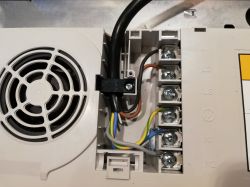
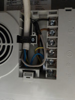
    Kamid1985
    Level 1  
    However, I did it as in the photo. Connection directly from the B16 three-phase protection to the board connector. The N wire must be connected to both N1 and N2 otherwise it will not flicker. I made it with the attached jumper.

Topic summary

The discussion revolves around the proper connection of the Whirlpool SMC 654 F / BT / IXL induction hob to a three-phase electrical installation. Users express concerns about the wiring process, referencing diagrams from the hob's casing and user manual. Some participants suggest consulting a professional electrician to ensure correct installation and warranty compliance. Others share their experiences, indicating that the hob can operate on two phases, with the third phase typically bridged with neutral. Key points include the necessity of connecting the neutral wire to both N1 and N2 terminals and ensuring proper bridging between phases as per the diagrams provided.
Summary generated by the language model.
ADVERTISEMENT