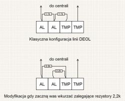
I meet many times on the forum with a request to draw a diagram of connecting a given detector to a given control panel, because the manual does not contain how to do it.
Yes, in the Satela control panel manual we will not find information on how to connect a DSC detector, but there is information on how to connect a Satela detector. And that's enough. This can be done by analogy.
It is enough to know that each detector, let's call it "universal", has the same and the same functioning basic contacts which, depending on the manufacturer, may be marked in different ways and placed in a different order.
Contacts that interest us
o two power contacts Here we indicate the power supply from the control panel in the appropriate polarity (plus to plus, minus to minus)
o two NC tamper contacts Closed when the detector housing is closed and reacting by opening to open it.
o two NC alarm contacts. Closed when the detector is powered and detects no motion, reacting by opening it to motion detection or removing the power supply.
Now let's look at some popular models:
Aqua Satel

NC, NC alarm contacts
TMP, TMP tamper contacts
COM 12V power supply
How do other manufacturers describe it?
DSC (e.g. LC 104 or PIR LC 100 dulana detector)

NC alarm contacts, C
T1, T2 tamper contacts
power supply -12+
As can be seen in relation to the Aqua detector, the alarm and tamper contacts have been swapped. There is also another NO / EOL contact, which should not be of interest to us with the standard connection of the detector to the control panel.
Vidicon Bingo

RELAY alarm contacts
TAMPER tamper contacts
power contacts -12+
Again, different order, different descriptions, this time for a pair of terminals, not single terminals, and this time two terminals (EOL), which are beyond the scope of our interests.
Pyronix KX15DD

ALARM alarm contacts
TAMPER tamper contacts
power contacts - and +
Bosch

NC, NC alarm contacts
T, T tamper contacts
power supply - and +
Which way to connect the detector to the control panel and how to do it
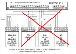
As you will see for yourself, the instructions contain several different examples of how to connect the detectors. If your control panel supports this type of parameterization (DEOL), forget about NO, NC, EOL. (below is a diagram from the Satel CA 5 control panel installer manual)
Advantages of DEOL (2EOL)
o The control panel, with such a detector connection and such configuration, detects three states on one line: normal state, violations and tamper.
o The status of the line on which the detector is connected is monitored all the time, regardless of whether the system is armed or not. It is necessary to know that the control panel will detect and report as tamper not only the opening of the detector, but also damage (interruption or short circuit) of the cable to which the detector is connected to the control panel.
o We save the control panel lines by implementing alarm and tamper signaling on one line.
At first, connecting a detector in DEOL (or 2EOL) configuration to the control panel may seem complicated. Nothing could be more wrong. It should only be remembered that one resistor connects one of the tamper contacts with the alarm contact, and the second one is parallel to the alarm contacts. You will find out about the benefits of such a system very quickly by diagnosing faults during the installation and operation of the system. To make it easier, more and more often manufacturers build resistors in the detectors and it is enough to put appropriate jumpers only during installation, remembering not to use both methods at the same time, i.e. not to put jumpers in DEOL and not to provide external resistors at the same time.
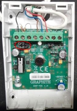
Examples. In both cases, pay attention to the position of the parameterization jumpers (circled in red)
Connecting the Satel Graphite detector in DEOL using built-in resistors. The jumpers are set to DEOL
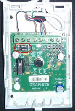
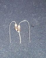
Connecting the Satel Graphite detector in DEOL using external resistors
Preparation of resistors
What we set on the control panel side:
o Input type. (its parameterization) The same as set by the detector resistors. In our case, it will be DEOL NC (in the case of control panels that provide DEOL NC and DEOL NO configuration) or simply DEOL in the case of other control panels.
o The appropriate type of reaction.
o If the detector is connected not directly to the control panel board, but to the zone expansion module, make sure that it has been properly added to the control panel. What range of input numbers does it support.
These are, of course, the basic zone settings, sufficient to test whether the detector has been properly connected. However, it is not always sufficient for the control panel to work as intended. But here I refer to the instructions.
Notes / FAQ
o DEOL = 2EOL. It's exactly the same.
o In the attached photos you can see jammed wires in the detectors. It does not look very elegant, but this way I wanted to draw your attention not to cut the free wires and leave some spare wire in the detector.
o The DEOL parameterization can also be used when connecting detectors without tamper contacts (eg most reed sensors). This makes sense because, as I wrote earlier, sabotage is not only opening the device, but also damage (short circuit, break) on the wires.
o DEOL parameterization is not supported only by very old control panels. But there are exceptions. Among those designed in this century that do not support this parameterization, one should first of all mention Satel Micra. It is not without reason that the installers prefer to stick to the name: "Communication module with the control panel option" We will rather not use DEOL parameterization by connecting the detectors directly to the communication module. But here too there are exceptions that make this possible, such as the Genevo GSM-8.
o In the detectors, we use resistors (with the same values) as imposed by the control panel. It is true that in most popular control panels from manufacturers such as Satel, Genevo, Ropam, 1.1k resistors are used for DEOL parameterization, but there are also control panels based on 2.2k (Risco) or 5.6k (DSC) resistors. In practice, this means that when connecting a Satellite detector, eg Graphite, to the DSC control panel, we will not use the resistors built into it, and we will have to use the ones attached to the control panel. Of course, the method of their assembly will be the same. However, we will use the built-in resistors in the Satellite detector, eg Graphite, by connecting it to the Genevo or Ropam control panel.
o When selecting a given parameterization of the detector (eg DEOL), remember to select the same parameterization in the settings of a given control panel input.
o If the detector reports tamper during violation (motion detection), it most often means that incorrect resistors have been used, resistors have been inserted into these terminals, and the resistor legs have not been properly seated in the detector connectors.
o If the detector is continuously violated, we first of all check if it has been properly powered.
o In more advanced exchanges, such as, for example, all "+" integrateds, you will also encounter something like TEOL (3EOL). This is nothing more than parameterization with the use of 3 resistors, where the control panel detects another state. This is used, for example, when connecting detectors with anti-masking (by the way, I suggest you take an interest in detectors with this function). The control panel zone operating in this mode detects, apart from tamper, violation, normal status, and also masking of the detector. In control panels that do not support TEOL parameterization, the detector anti-masking output is simply connected to a separate control panel input.
Good luck!
.................................................. ..........................
Advertisement
Also read:
How to connect two alarm detectors on one cable. How to connect two detectors to one zone of the control panel and what are the consequences? Collection of topics
We invite you to read the other guides, highlighted topics, articles in the field of security systems such as intercoms, gate and barrier automation, alarm systems, cameras, access control:
Security Systems Tutorials
If you do not find the answer to your question in the above-mentioned topics, please visit the forum:
Security systems
We also encourage you to visit the General Guides section, where you will find materials from other forum sections, including those for people starting their adventure with electronics:
General Tutorials


