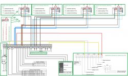
Hello, can any of you check if I drew the detector and siren connection to the SATEL Perfecta 16 control unit correctly?

1x Satel Perfecta 16 alarm control panel
1x LCD keypad for Satel PRF-LCD system operation
4x Paradox PRO Plus indoor motion detector
1x acoustic-optical siren SL-550
1x 40VA transformer
1x 7.2Ah / 12V backup battery
1x ANT-GSM-I dual-band antenna
I will be grateful for the amendment, best regards
.................................................. ..........................
Announcement
Also read:
Satel Perfecta alarm control panel, configuration - selected issues Collection of topics
Outputs (programmable and not only) of control panels
How the control panel alarm outputs work
Connecting any detector to any alarm control panel - guide
How to connect the siren to the alarm control panel - guide
We invite you to read the other guides, highlighted topics, articles in the field of security systems such as intercoms, gate and barrier automation, alarm systems, cameras, access control:
Security Systems Tutorials
If you do not find the answer to your question in the above-mentioned topics, please visit the forum:
Security systems
We also encourage you to visit the General Guides section, where you will find materials from other forum sections, including those for people starting their adventure with electronics:
General Tutorials


