logo elektroda
logo elektroda
X
logo elektroda

SOLAR TRACKER Project Prototype: IC TDA2822, PCB Design & Schematic Review Needed

weteranPL 19407 6
ADVERTISEMENT
Treść została przetłumaczona polish » english Zobacz oryginalną wersję tematu
  • #1 18693402
    weteranPL
    Level 7  
    Hello
    I'm presenting the project SOLAR TRACKER based on an integrated circuit (TDA2822 amplifier). The SOLAR TRACKER PCB prototype and diagram were designed with sun tracking in mind, which allows the solar panel to charge electricity on sunny days.
    Is the PCB design and schematic correct?

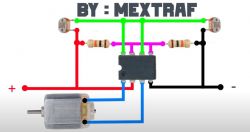
    Project base source (SOLAR TRACKER)

    [youtube]https://www.youtube.com/watch?v=Y0GolIefeYg
    [/youtube] Solar Tracker circuit diagram with TDA2822 amplifier, resistors, photoresistors, and a motor.
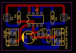
    PCB prototype and diagram that I designed:
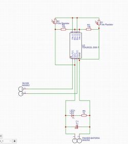
    Electrical schematic of a solar tracker controller with TDA2822L IC. PCB design for a solar tracker with components such as U2, LED1, resistors R1-R4, and a 100UF capacitor.
  • ADVERTISEMENT
  • #2 18693552
    Anonymous
    Level 1  
  • ADVERTISEMENT
  • #3 18696489
    weteranPL
    Level 7  
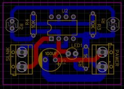
    I routed the paths differently, is it better in this project?

    SOLAR TRACKER Project Prototype: IC TDA2822, PCB Design & Schematic Review Needed
  • ADVERTISEMENT
  • #4 18696513
    pawel_wzts
    Level 11  
    I understand this is for azimuth tracking. I would also add a second system to track the angle of inclination. I wonder how it will handle the day-night-day transition, but the concept is interesting. Let me know when you run it.
  • ADVERTISEMENT
  • #5 18696535
    weteranPL
    Level 7  
    And how can I connect this inclination angle tracking system to the system I designed? You've got it in the video, roughly how it works.
  • #6 18775655
    weteranPL
    Level 7  
    Do you need a controller and a stepper motor power supply for this SOLAR TRACKER?
  • #7 18775716
    Anonymous
    Level 1  

Topic summary

The discussion revolves around a prototype for a solar tracker project utilizing the TDA2822 integrated circuit. The author seeks feedback on the PCB design and schematic, which is intended to optimize solar panel charging by tracking sunlight. Initial responses highlight issues with the PCB layout, such as unnecessary dual-layer design, duplicated tracks, and suboptimal component arrangement. Suggestions include improving routing to avoid path crossings and considering the addition of an inclination angle tracking system. The conversation also touches on the need for a controller and stepper motor power supply, emphasizing that a stepper motor requires a compatible driver for proper operation.
Summary generated by the language model.
ADVERTISEMENT