logo elektroda
logo elektroda
X
logo elektroda

Another Solar Tracker - controller and description of the structure

SylwekK 6120 25
ADVERTISEMENT
Treść została przetłumaczona polish » english Zobacz oryginalną wersję tematu
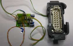
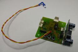
  • Printed circuit board with electronic components and a wire ending with an LED.

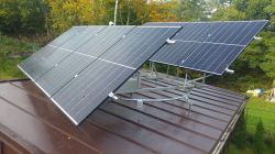
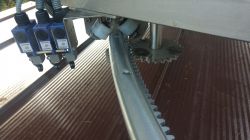
    Today I am presenting another controller of my creation for the solar tracker (the first one from 2011 is described here: Photovoltaic panel turntable controller ). This time, a rudder designed for a friend who made the mechanics himself based on an old trampoline, or more precisely, its rim with a welded-in gear. Everything is placed on a relatively flat garage roof, mounted on pins with stiffening reinforcements. They are not in the attached photos yet (actually there is one, the rest are being made). The structure with panels rolls on rollers, and there are similar rollers on the bottom to prevent the wind from blowing away the "sail". The rotation could be 360 degrees, but for obvious reasons it is limited to about 260-270. If by some miracle the limit switches do not work, the rack will simply run out and the movement will stop, and the engine will turn off automatically after a short time (time protection in the program will activate). The controller is single-axis (panorama only) - these were the assumptions.
    It would seem that tracking the sun could be done using one or two comparators and the matter would be solved - nothing could be further from the truth. As my experience has shown, a good algorithm means failure-free and fruitful operation of the whole. There are two schools of following the sun: 1-tracking, 2-clocking. I support option 1 and no one has yet had strong enough arguments to convince me to choose option 2.
    So what does my driver have in it? It is based on Atmega168 (smd), and the program takes about 8kb written in C (predecessor in BASCOM. First of all, all movement options, buttons, etc. are protected by a time delay, e.g. there is no sudden change of direction without waiting first at least 1-2 seconds (longer in some situations).
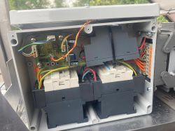
    The controller manages two 24V relays, switching on and changing the direction of a three-phase motor (a friend had one and it suited his project). If there was a sudden turnaround without time delay, it is easy to imagine that even a strong fuse would blow.
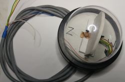
    The light sensor consists of two phototransistors placed with a partition in the dome camera housing (hermetically improved). This casing worked well in the first project, so why drill down.
    There is no additional photoresistor, which is sometimes found in other controllers of this type, to determine the parking level, and I am surprised by such solutions, because it is completely pointless, having two photoelements on board, which are perfectly capable of assessing the light level. The use of phototransistors instead of photoresistors as directional sensors is also important, because it is impossible to wake up the system by shining a typical, popular LED flashlight on the sensor, even if someone wanted to do it out of curiosity or malice.
    At the startup and installation stage, I updated the software a few times, correcting minor errors or adding simplifications, but this is a normal process in a living organism, because the fact that everything works beautifully on the desk is only a theory, and practice usually quickly verifies it.
    Currently, the positioner copes well with the sun, gets up and goes to sleep when the time comes, and the sleeping position in this (as well as in my first tracker) is the southern position. This is an almost ideal position for our region, because 90% of the wind blows from the west, sometimes slightly from the southwest, and it is also an excellent anti-wind position (the panels facing the wind offer little resistance).. Plus, it's the best place to start tracking. No, not the eastern one, I don't agree with that and no one will convince me that the eastern part is better.

    Main features of the controller:
    - tracking in both directions east - west,
    - on-demand programming of the tracking threshold (brightness level at which work starts and ends) stored in the eeprom memory,
    - tracking interval of at least 10 minutes (fixed), sometimes depending on the sunlight or lack thereof, after the countdown there is a waiting time for stronger light,
    - protection against momentary flashes (the sensor must be in a clear lighting state for at least 2 seconds),
    - manual positioning with tracker buttons in both directions (e.g. for maintenance purposes),
    - time protection against failure to reach the target (tracking, parking) and related personalized alarms to quickly determine the cause of the fault,
    - manual shortening of time delays (tracking interval, parking on demand, wake-up) for maintenance and testing purposes using a button,
    - each controller state is signaled by an individual, very intuitive and clear LED blinking time combination (9 states),
    - the parking position is determined by an additional switch (in this case the southern one),
    - all limit switches are connected to the processor via optocouplers for safety reasons (e.g. induction of voltages in the cables).

    The rudder also has an anti-wind input prepared and it is partially programmed (the executive part, i.e. parking on the southern end switch regardless of which side of the end switch it is located on), but my friend does not have any sensor at the moment and does not know the parameters to which the program should respond, so for now the input is unused and inactive.

    I do not share the program. Let the above description be an inspiration for someone who would like to make such a rudder but does not know what functions to equip it with.
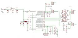
    Electrical schematic of a solar tracker controller with ATmega168 microcontroller.

    And finally, a few photos.

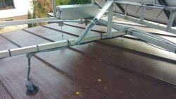
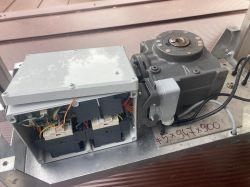
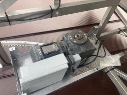
    Photovoltaic panels mounted on a garage roof with a rotating mechanism. Controller block mounted on a metal structure of a solar tracker with visible cables. Panel tracker control system with gear and sensors. Solar panel mounting structure on a roof.
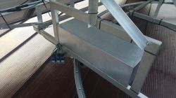
    Solar tracker controller inside a housing with visible wires and components. View of the interior of the solar tracker controller housing. Geared motor with mountings on a metal structure.
    The image shows an electronic controller module with a multi-pin connector and colored wires attached. Solar sensor with two phototransistors in a dome-shaped enclosure.

    The video shows a part of the ride during calibration right after turning it on.


    Cool? Ranking DIY
    About Author
    SylwekK
    Level 32  
    Offline 
    SylwekK wrote 2753 posts with rating 2743, helped 82 times. Live in city Lipsko. Been with us since 2007 year.
  • ADVERTISEMENT
  • #2 20788486
    Shadowix
    Level 31  
    Cool driver. What is the total cost of RBH? Why not something industrial? Even this Logo! to be enough, you can add a preview online, etc., etc. I don't like the use of the yellow-green cable to control the contactors (by the way, an interesting option of connecting them vertically on Schneider) and the lack of a DIY diagram ;)
    As for the mechanical structure, I hope it will be supported quickly, because the pins look very weak. The same applies to protection against falling off the wheel - I simply recommend a steel cable to the roof/lower structure. At most, the wind will knock the panels off the rollers, but it will not fly.
  • #3 20788626
    Sofeicz
    Level 20  
    And how does tracking perform in full cloud cover, when it is difficult to obtain a differential signal from phototransistors?
  • #4 20788924
    SylwekK
    Level 32  
    Shadowix wrote:
    What is the total cost of RBH?

    The electronic side - costs about PLN 100, but the execution (diagram, board, soldering) requires a day's work. The program took a total of 1-2 days (including tests).
    The rest (mechanics, box, contactors, etc.) was assembled by a friend himself.

    Shadowix wrote:
    Even this Logo! If that's enough, you can add a preview online, etc., etc.

    Maybe it would be enough, BUT...
    - it wouldn't necessarily be cheaper, because the cost of such drivers is not symbolic, and at least 8 inputs and 3 outputs are needed;
    - first of all, you need to know how to program it...
    I am more or less familiar with the principles of PLC programming and it seems unlikely that I would be able to implement the functionality that I created directly in C on a small board in 200 blocks.
    - the need to view the network is replaced by one LED, which I can immediately check with my eyes without connecting to the network or taking out my phone or computer :) This LED tells EVERYTHING I need to know about the controller's operation.

    Shadowix wrote:
    I don't like the use of the yellow-green cable to control the contactors

    Without exaggeration, this is not a thriller film in which the main character has to cut a red or blue wire :) I don't want to believe that when you make something for yourself, where no one will probably look, you always run to the store to buy 30 cm of blue to combine some crap when you have a roll of yellow-green at home. If it was a complicated box, you are of course right, it is worth maintaining some standards, but here, after opening, there are only two contactors and you can clearly see what is connected to what.

    Shadowix wrote:
    As for the mechanical structure, I hope it will be supported quickly, because the pins look very weak. The same applies to protection against falling off the wheel

    Yes, I also pointed out to my friend the stiffness of the structure, and he also sees how it is, which is why he started making supports. One of the photos shows one already installed - and it does its job.
    However, the stroller will not fall or be blown away, because there are rollers at the bottom (see the video).

    (I added the diagram to the first post)

    Sofeicz wrote:
    And how does tracking perform in full cloud cover, when it is difficult to obtain a differential signal from phototransistors?

    There's probably no problem with that. The brightness level is programmed to actually follow the energy, not to find a slightly brighter spot. After the calculated interval, if there is cloud cover below the sensitivity level, the system will wait and immediately after the sun appears, it will adjust itself as it should and then wait for another 10 minutes. If the gray light persists, parking will take place after an hour. If the parking is during the day and the sun finally appears, of course the rudder wakes up and starts tracking.
  • #5 20789021
    Sofeicz
    Level 20  
    What is the estimated energy cost of such control?
    How much energy does the operation of the controller and actuators consume?
    Did you count it?
  • #6 20789034
    SylwekK
    Level 32  
    @Sofeicz, I didn't count. I'm taking a common sense approach here :) Taking into account the 10-minute interval with several seconds of movement and the correct setting of the tracking threshold, the cost of the turntable operation is negligible, not to mention the milliamps consumed by the controller itself. I say this based on the example of my first project, and the situation here is analogous. However, I estimate the increase in energy yield from panels on a sunny day to be at least 40%. In this particular case, taking into account the changes in settlements for energy produced from January (variable price depending on sunlight), it can be expected that the profit will be even greater.
  • #7 20789546
    krzbor
    Level 27  
    SylwekK wrote:
    I support option 1 and no one has yet had strong enough arguments to convince me to choose option 2

    Maybe I'll try :)
    In option 1, the main problem is the possibility of contamination of the optics. If a bird leaves its white substance on the western or eastern part, the system will immediately stop working properly. Likewise if a stray leaf sticks there. Generally, any asymmetric contamination will cause problems.
    I would make the clock system like this - I would place reed switches around the perimeter - the two extreme ones correspond to sunrise and sunset at the summer solar solstice, and the additional ones I would place at 6, 9, 12, 3 and 6 p.m. All "sunny" times, i.e. 12 o'clock means the zenith. Control based on a battery-backed RTC clock, and the whole thing controlled from ESP8266 (AP mode), so that the correct time can be set from a cell phone (and from a distance). The position is corrected every 1/2 hour by counting the engine power time - of course, every 3 hours there will be synchronization anyway.
    The system can be equipped with self-correction - time corrections of shifts in individual time intervals can be saved in the RTC RAM. Such adjustments may be necessary due to rotational irregularities related to temperature and component wear.
  • ADVERTISEMENT
  • #8 20789654
    SylwekK
    Level 32  
    Well, sorry, but the complexity of the system you describe begs for systematic failures :) Still not convinced. In fact, most opponents of tracking write about sensor contamination. Pay attention to its dome-shaped structure, on which practically everything flows and is extremely uncomfortable for birds to rest. Thanks to the large size of the dome, even small impurities that would be found there are practically irrelevant to the average brightness. And now the best part - everything that has been written so far about dirt never happened on my first version of the positioner, which has been on the roof for over a dozen years to this day. Oh, and what about saving the clock positioner? In all the descriptions I read, the main argument was the constant current position of the sun even on a cloudy day, that the sun will come out and the panels will collect light. So I'm asking, why should you be a free rider and waste your energy on something that doesn't exist? :)
  • ADVERTISEMENT
  • #9 20789733
    krzbor
    Level 27  
    I don't see any room for systematic failures. Reed switches are a very good solution - they are effective and practically failure-free. Basically, you can reduce their number by 2, i.e. make synchronization intervals every 4 hours: 4, 8, 12, 16, 20 (where 4 and 20 are also "ends"). If ESP is within the range of the home WiFi network, you can use a normal connection instead of the AP mode and then we get rid of RTC (replace it with NTP) and we can additionally report faults to the server (e.g. failure to set the position within a given time, which indicates, for example, that the tracker is blocked) . The current for positioning will be lower than in your solution, because when we turn the system, we always do it by a specific angle and always in one direction (and back at night). However, if your experience with the dome is positive, then the biggest problem is indeed eliminated.
  • #10 20789835
    Sofeicz
    Level 20  
    How did you solve the problem of defining hysteresis?
    I once saw a similar controller that had the disadvantage that when reaching the target point, it fell into oscillations caused by too narrow hysteresis.
  • #11 20789841
    krzbor
    Level 27  
    You can also do it differently - add only the limit switches (actually, you should only add one "morning"), and determine the position using the light barrier installed on the lower gear. Then we simply count the "teeth". This will enable very precise positioning. We only have one limit switch and one barrier. In the event of a power outage or processor restart, we return to "morning" and start positioning to the current time.
  • #12 20790222
    slaw0
    Level 15  
    krzbor wrote:
    You can also do it differently - add only the limit switches (actually, you should only add one "morning"), and determine the position using a light barrier installed on the lower gear. Then we simply count the "teeth". This will enable very precise positioning. We only have one limit switch and one barrier. In the event of a power outage or processor restart, we return to "morning" and start positioning to the current time.

    For tooth counting, an inductive sensor reacting to metal or an encoder on the motor will be better.
  • #13 20790233
    Anonymous
    Level 1  
  • #14 20791021
    gimak
    Level 41  
    cefaloid wrote:
    It's simpler and cheaper to put that money into more panels. Then the profit will also increase...

    If I were to play with these blocks on a larger scale, because I play on a micro scale, that's why I observe topics like this and I had the right conditions, I would rather choose trackers, and rather two-layer ones. There are two arguments for this:
    1. The same energy can be obtained from a much smaller panel area.
    2. The distribution of power obtained from the panels on the trackers during the day will be much more even than when the panels are stationary. This is confirmed by my results obtained at the beginning of my adventure with PV panels. From a 10W/12V panel and a current Imp = 0.57A, with perpendicular lighting, on a sunny day, the following results: at 7 I=0.5A, at 12 I=0.57A, and at 18 I= 0.49A.
    Maybe this argument is irrelevant for on-grid installations, where the time distribution of the energy obtained is irrelevant, but it becomes important for off-grid installations.
    As for the tracker control itself, in the horizontal plane I would rather use clock control, and in the vertical plane, sun tracking.
  • ADVERTISEMENT
  • #15 20791022
    SylwekK
    Level 32  
    Sofeicz wrote:
    How did you solve the problem of defining hysteresis?
    I once saw a similar controller that had the disadvantage that when reaching the target point, it fell into oscillations caused by too narrow hysteresis.

    There is no problem with hysteresis, because it takes a stable 2 seconds to change the sensor state, and after making a movement, the lock is immediately activated for 10 minutes.

    krzbor wrote:
    You can also do it differently - add only the limit switches (actually, you should only add one "morning"), and determine the position using the light barrier installed on the lower gear. Then we simply count the "teeth". This will enable very precise positioning.

    My first solution is to count impulses from the actuator and is used to determine the parking position. The calibration signal comes, of course, from the limit switch. In this version it was easier to simply earn a stopping point.

    cefaloid wrote:
    How many kilowatts does it take to turn the tracker? Does it really matter?

    If something runs pointlessly, e.g. without producing energy for two weeks, it probably makes sense not to run it :)
    cefaloid wrote:
    But to the point: no one can convince you to choose 'option number 2', i.e. clock-based positioning.

    Well, apparently there are no good arguments for doing so :)
    cefaloid wrote:
    This made sense 20-30 years ago when panels were expensive. Today they are cheap. It's simpler and cheaper to put that money into more panels. Then the profit will also increase...

    And here I am even willing to agree with you under certain conditions. If someone has space to install an additional battery of panels, then yes. However, a larger number of panels means a greater risk of destruction by possible hail or other destructive phenomena (the positioner itself will usually not suffer in such situations). And probably the most important thing - the whole game makes sense when you do it wisely on your own, then you can really reduce the costs to a profitable level, especially since the profit from tracking is at least 40%, as I wrote earlier.
  • #16 20791658
    Anonymous
    Level 1  
  • #17 20791702
    SylwekK
    Level 32  
    cefaloid wrote:
    Are you sure? Please correct me if I'm wrong, but aren't tracker installations most often made in such a way that the panels are placed 'lying down' during windy conditions?

    It depends on who writes the software :) Most of the trackers I've read about do just that, i.e. place the panels, while I position them quite sharply vertically and sideways to the wind. This solution was already available in a version from a dozen or so years ago - I recommend reading the link provided in the first post. In that topic, I wrote elsewhere about a certain storm that devastated our area - only in my neighborhood it ripped off two roofs, damaged street infrastructure and broke hundreds of trees. The panels were then in a position of about 70 degrees vertically and at an angle of about 30 degrees to the wind direction (i.e. not yet ideal), and yet nothing happened to them at all. In my trackers, the user defines the anti-wind position based on the observation from which side the wind blows most often. In my region, the wind usually blows from Z and PdZ, so the south setting seems to be the best. This year, exactly 11 years ago (the difference is only 9-10 hours!) After the mentioned storm, the wind blew again, although it was a bit weaker, but the tree broke and I had the neighbor's asbestos stuck 20 cm into the ground, and the panels are still on the roof. Nothing but enjoyment :)
  • #18 20791823
    sq3evp
    Level 37  
    Nicely made, I've seen a similar diagram - 4 phototransistors that can be placed in two planes.
  • #19 20792031
    SylwekK
    Level 32  
    Thanks :) Initially, I was going to make a universal version with two axles, but my friend doesn't even plan on changing the design, so I only made him a left-right one.
  • #20 20792121
    sq3evp
    Level 37  
    It is much more difficult to follow the sun in two planes - especially mechanically.
    Once at school we had a purely conceptual project to think about how to do it using op. amps as follow-up regulators.

    No controllers, only fully analog, maybe primitive, but sometimes there is no need to use a cannon to hunt flies. Old analog electronics often give much better results. In the past, a flasher was built on 2 transistors, but today they use a controller.
  • #21 20793858
    SylwekK
    Level 32  
    @sq3evp, from the software side it's no problem, but mechanically it's 100% right - the entire structure needs to be well balanced and bearinged, and everything must be durable and stable.

    sq3evp wrote:
    No controllers, only fully analog, maybe primitive, but sometimes there is no need to use a cannon to hunt flies.

    I'm also not a fan of charging the uC to symbolically blink the diode, and if I can make the circuit quickly without a programmer, I try to do it. However, if you want to do more advanced logic, it is simply much easier and safer on a uC, but if you need to make any changes in the way it works, it is only cosmetic, and not, for example, sawing a board and an extension with a handful of elements on a spider. :)
  • #22 20794555
    SylwekK
    Level 32  
    A friend just sent me a video of the teacker waking up after parking overnight. A shot from literally half an hour ago as I write this post. Apart from the losses due to the covered second row of panels (I don't remember if the two independent streams are connected), the production is quite decent compared to if they were rigidly placed south.


  • #23 20795907
    sq3evp
    Level 37  
    It looks nice.
    If there was adjustment in the Y plane, the panels would be slightly more vertical and both would be properly illuminated
  • #24 20797975
    Sofeicz
    Level 20  
    In this configuration - not really.
    The panels are close enough to each other that at small angles one covers the other.
    In my opinion, it would be better if the panel "closer to the Sun" rose later than the next one.
  • #25 20818297
    mfac
    Level 17  
    Epic! Respect!
    I once had an idea to build three rows of panels on the roof of a farm building, sloping to the west, with the top mounted on wheel bearings from a passenger car and the bottom running on guides or glides. This was how it was supposed to travel from the south-east to the south-west, and the vertical inclination would also be somehow driven. Unfortunately, due to lack of time and rather low profitability of such a combination, I am currently creating an installation with a constant azimuth and inclination set manually once a quarter in one of three positions - winter/spring-autumn/summer, respectively.
    And now back to your device -
    1. Do you have contactors between them protected against simultaneous switching on using auxiliary contacts? I understand that the program does not allow for simultaneous control of both transistors, but UC damage or transient states at the outputs do occur and it would be good if the control of one contactor went through the normally closed contacts of the other.
    2. Is the filtration of the voltage supplying the analog part of the uC really well done? Shouldn't the choke precede the capacitor?
    3. I would move the control buttons outside. They may be rarely used, but why open the can every time?
  • #26 20819010
    SylwekK
    Level 32  
    @mfac, thanks :)
    mfac wrote:
    1. Do you have contactors between them protected against simultaneous switching on using auxiliary contacts? I understand that the program does not allow for simultaneous control of both transistors, but UC damage or transient states at the outputs do occur and it would be good if the control of one contactor went through the normally closed contacts of the other.

    I don't know how my friend connected these contactors - probably standardly, but from the program level there is no chance that both of them would be triggered. Not only are both of them always turned off first, but there is ALWAYS a time delay (min. 2-3 seconds) before one of the directional relays is turned on. This applies to both automatic and manual traffic. If the uC were damaged, and in my entire microcontroller career the processor in the controller failed only once, and that was at my own request (I didn't seal the housing and poured water on the controller) and somehow two relays were tripped, it would trigger the overcurrent protection and that's all it was supposed to do. place at the beginning when testing the tracker - I forgot about the delays in some places and it changed direction too quickly :)
    mfac wrote:
    2. Is the filtration of the voltage supplying the analog part of the uC really well done? Shouldn't the choke precede the capacitor?

    In fact, the diagram does not include one additional cap, which should be directly between AVCC and GND after the choke. In this case, however, it does not have a significant impact on the operation of the system, because the power supply is filtered well enough anyway. Either way, it's a good idea to have 100nF there.
    mfac wrote:
    3. I would move the control buttons outside. They may be rarely used, but why open the can every time?

    You don't go there often. After startup, the system is virtually maintenance-free. I added the control mainly for testing and maintenance purposes, e.g. when I needed to turn the set to correct something on the panels or drive. I would only place the LED in a more visible place, but my friend says that it is enough for him :)

Topic summary

The discussion revolves around a custom solar tracker controller designed by the author, featuring a mechanical structure based on an old trampoline rim. The controller's electronic components cost approximately PLN 100, with additional assembly and programming time required. Participants raise concerns about the mechanical stability of the structure, the effectiveness of tracking under cloudy conditions, and the energy consumption of the system. Various suggestions for improving the tracking mechanism are proposed, including the use of reed switches, light barriers, and inductive sensors for precise positioning. The conversation also touches on the advantages of using solar trackers versus fixed panels, particularly in terms of energy yield and efficiency.
Summary generated by the language model.
ADVERTISEMENT