logo elektroda
logo elektroda
X
logo elektroda

Simple solar tracker on the L272M for controlling solar panels.

heniek07 14697 29
ADVERTISEMENT
Treść została przetłumaczona polish » english Zobacz oryginalną wersję tematu
  • #1 17694186
    heniek07
    Level 20  
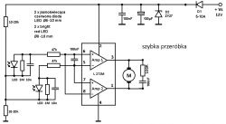
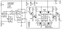
    I present a diagram of a solar tracker based on the L272M chip and bright red LEDs. The system worked when the LEDs were open a small angle and constantly illuminated by the sun. It also responded correctly when the LEDs were soldered straight and covered with the diaphragm. If the LED was coming out of the shadow, the wiper motor was turning in the right direction, if both were in the shadow it was standing.
    The version with an H bridge on car relays has been tested by me in a spider mount. The relay consumed a current of 120-140 mA. L272M is a double power operational amplifier according to catalog notes with a load of 0.7-1A depending on the manufacturer. I found it in the motor of the headlight adjustment motor of cars, VAG flu from the 90s, produced by Bosch. There he acted as a DC motor driver. There are TLE4201 - 4206 chips in Hella motors. I burned TLE4201 during tests. I had only one motor with TLE4201 among 6 bought on the road for PLN 25. Both types of integrated circuits are suitable for this solution, the only difference is the housing - the L272M is smaller (DIP-8). I was dealing with the headlight adjustment motors because they are some servos and I was going to use a similar solution for horizontal rotation of photovoltaic panels. At the moment it should be 90% successful. The control will be a clock mechanism using a servo built on the above-mentioned operational amplifier. I am going to receive feedback on the rotation by means of the vertical Żuk rear bridge, which was left to me after the construction of the tractor. https://www.elektroda.pl/rtvforum/topic1352007-60.html#7700395
    According to the presented diagrams, the solar tracker would control the photovoltaic panels only in the vertical axis. Which does not disqualify it from being used in both axes - I hope so. I used the L272M because its outputs can be used to control the H-bridge with car relays, which in my opinion greatly simplifies the design. Very few components are needed, and the system does not require any adjustments. Currently, I have little time and I am more concerned with the mechanics of my turntable. Before this solution was created by trial and error, I made a few prototypes. I even checked the 40-year-old solution, which was developed by Jeff Damm in 1978, then the reworked scheme was included in Nowy Elektronik 4/2004 (with a mistake). The problem was with alignment. https://www.freeenergyplanet.biz/homemade-windmachine/an-active-solar-tracking-system.html
    https://www.elektroda.pl/rtvforum/topic2307857.html#10957958
    https://www.elektroda.pl/rtvforum/topic2307057.html#10953977#10953977
    This is quite a time-consuming method, and at times stressful and annoying.
    Accordingly, I have a request to the forum community. If any of the forum members has the time and "processing capacity", and is also interested in the solar panels following the sun, please make a prototype and share your observations. Useful modifications will also be appreciated. I am not a professional electronics engineer , I created a solution based on news from the Internet and textbooks from the last century (mid-1980s). Below is a diagram. Regards, Heniek. :D I improved the producers that I replaced earlier - 1/18/2019 :cry:
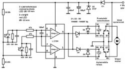
    Simple solar tracker on the L272M for controlling solar panels.
    January 13, 2019
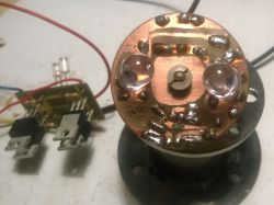
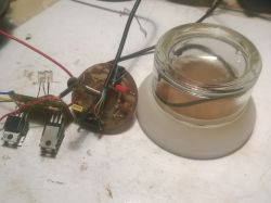
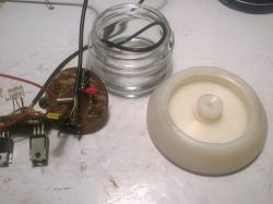
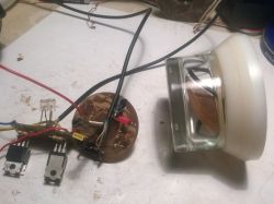
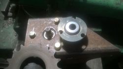
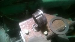
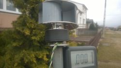
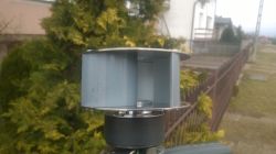
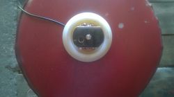
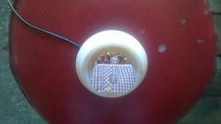
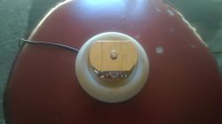
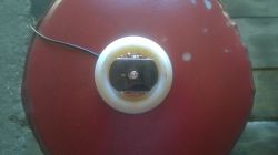
    I mobilized a little and rummaged in the boxes. This is how my prototype "spiderwebs" look like. I am going to close the electronics with the integrated circuit and the sensor on the LEDs in a glass jar of some wife's cream. It had a single-turn thread, so it was easy to add a nut.
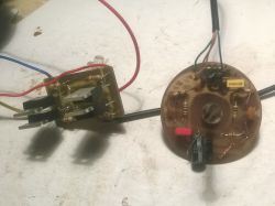
    Simple solar tracker on the L272M for controlling solar panels. Simple solar tracker on the L272M for controlling solar panels. Simple solar tracker on the L272M for controlling solar panels. Simple solar tracker on the L272M for controlling solar panels. Simple solar tracker on the L272M for controlling solar panels.

    This is how the bulb from the workshop lamp works. The wiper motor comes from the Golf 3 and required a bit of preparation - it was two-speed, as is the case with the motors from the FSO 1500, the Polonez.
    https://youtu.be/ri6OLR9TcGU
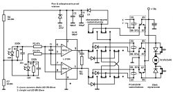
  • ADVERTISEMENT
  • #2 17717827
    SylwekK
    Level 32  
    Why not phototransistors (very sensitive anyway) but ordinary light emitting diodes? From what I can see, the system does not have any time protections (these capacitors on the WO inputs will probably do a lot here) and it will want to spin even with short-term flashes at night. In addition, the search for the sun in this system will last practically until dusk, which is when the search is no longer profitable.
  • ADVERTISEMENT
  • #3 17717857
    heniek07
    Level 20  
    Buddy SylwekK, I don't know what to say to you. Don't be offended, but re-read the end of my statement. Regards.
  • #5 17718942
    heniek07
    Level 20  
    Thanks, my friend Sylwek, that you dared to speak. :D Thanks to you, maybe the topic will come alive a little. While writing it, I was hoping that someone might modify my diagram and throw in a "ready-made" one, or that someone would suggest something equally simple - that is, it would also speed up my work. The foundation in the garden has been waiting for a year and a half, and 6 panels in a shed for 8 months - it's a bit of a shame. The structure would have to be set up before planting vegetables. Right now, I'm really into mechanics. Let's say today I finished something like flipping panels horizontally. It will probably be a replacement for a Bosch wiper motor from German cars, because I suspect it will be more efficient. At least the idle current needs less than that in the photo. Your solution is great. I watched them quite a long time and repeated today. I have an East-West roof and that's why I'm using a solar tracker in the garden. Regards. :D
    Simple solar tracker on the L272M for controlling solar panels. Simple solar tracker on the L272M for controlling solar panels.
  • #6 17718966
    soniak2
    Level 21  
    Gentlemen, how do you solve the installation of the pinion shafts to the tapered and inch threads in the wiper motor?
  • #7 17719881
    heniek07
    Level 20  
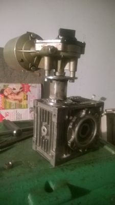
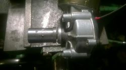
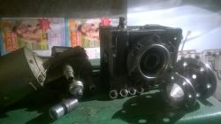
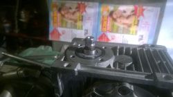
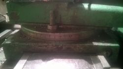
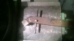
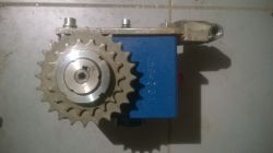
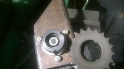
    I am posting a few photos, they should brighten up a bit. There were sleeves with Polish engines, because the engines come from withdrawn hospital equipment and not from cars. One seemed to be controlling the patient's bed cushion, the other one was controlling a pump. I drilled the nuts for the horizontal controls. As you can see, not all of them were successful - the best one was chosen. The angle and the hastily constructed knife from the drill are in the photo. By turning at an angle, using the manual feed of the post, you can similarly clamp what you need. The fact that a replaceable gear is mounted on the engine is an unfortunate accident at work. When making elements for the worm gear intended for vertical control, I chose the hole for the shaft and used the made element at the engine. I rolled it over and put it while hot on one of the aforementioned sleeves. In this transmission, I wanted to have the possibility of interchangeable gears to experimentally check which would be better, after all, all this is a prototype. Best regards, I wish you fruitful work and as few mistakes as possible. :D
    Simple solar tracker on the L272M for controlling solar panels. Simple solar tracker on the L272M for controlling solar panels. Simple solar tracker on the L272M for controlling solar panels. Simple solar tracker on the L272M for controlling solar panels. Simple solar tracker on the L272M for controlling solar panels. Simple solar tracker on the L272M for controlling solar panels. Simple solar tracker on the L272M for controlling solar panels. Simple solar tracker on the L272M for controlling solar panels. Simple solar tracker on the L272M for controlling solar panels.
  • #8 17723385
    jarek_lnx
    Level 43  
    The circuit with MOSFETs when switching will make short short circuits of a few microseconds due to the activation of all four MOSFETs.
  • #9 17724460
    heniek07
    Level 20  
    Buddy Jarek, thank you for your interest. Please do not be offended by what I write. Your post did not help me, I do not expect such help. As I wrote, I am not a professional electronics engineer. How can you draw the remakes. If I could and knew, the scheme would probably look a bit different. My power supply has a current limit of 2A (it is a little bit for a wiper motor) and yes, when the motor is started, the overload diode will flash a little, but when turning off I have not noticed anything like that. Best regards and I am asking everyone for specific help. :D

    Added after 53 [minutes]:

    And that's how it was in the original, at the exit , in controlling the car's headlight with a tiny motor.
    Simple solar tracker on the L272M for controlling solar panels.
  • ADVERTISEMENT
  • #10 17725245
    jarek_lnx
    Level 43  
    heniek07 wrote:
    Buddy Jarek, thank you for your interest. Please do not be offended by what I write. Your post did not help me, I do not expect such help.
    I wrote to let you know that such a problem exists, that when you power from a power supply with a current limitation, it is ok, but the power supply from, for example, a car battery may cause damage, because a very large current flows can cause EM interference to nearby devices, you can also expect power surges when the transistors will interrupt the short-circuit current, the most popular solutions are timing circuits delaying the switching on of the transistor and only switching on, the solutions I can quickly come up with are not as simple as you would expect.
  • ADVERTISEMENT
  • #11 17725332
    heniek07
    Level 20  
    Thanks a lot for now. How will I organize the battery, I will check it with some protection, let's say 4 - 8A. Knocks what else there is a solution on relays.

    Added after 8 [hours] 19 [minutes]:

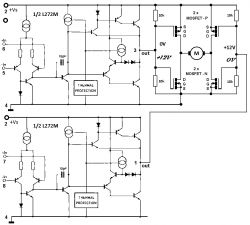
    Welcome back. I found my old pen-drive with the schematic where I analyzed the H-bridge on MOSFETs. Maybe some of you will help now?
    Simple solar tracker on the L272M for controlling solar panels.
  • #12 17728635
    heniek07
    Level 20  
    Thanks colleagues for your interest. I did not make experiments. Today I measured the voltage at the outputs of the amplifiers, when the engine is not working, both are 12V. For the H-bridge with MOSFET, this is hardly advisable. So I delete the diagram from the post creating the thread. I believe it is incorrect. :cry: I leave the diagram with car relays. Relay solutions are used in commercially sold sets, so they can stay here as well. If anyone is able, please modify the "input" of the circuit. :D
  • #13 17728655
    jarek_lnx
    Level 43  
    heniek07 wrote:
    I did not make experiments. Today I measured the voltage at the outputs of the amplifiers, when the engine is not working, both are 12V. For the H-bridge with MOSFET, this is hardly advisable.
    Not true, it is correct, the motor has 0V whether it is 12V and 12V or 0V and 0V
  • #14 17728663
    heniek07
    Level 20  
    I agree with you, but I mean the MOSFET control itself.
  • Helpful post
    #15 17728674
    jarek_lnx
    Level 43  
    heniek07 wrote:
    Welcome back. I found my old pen-drive with the schematic where I analyzed the H-bridge on MOSFETs. Maybe some of you will help now?
    As for this, you don't need an internal schematic of the WO to analyze how it works, just general knowledge of the operation of the WO that they have high gain and minimal variation on the inputs gives the output saturation.
  • #16 17728682
    heniek07
    Level 20  
    Thanks Jarek. For now, let's leave it like this: It works fine on the relays. The diodes will direct the current to the appropriate coil depending on which direction it will flow from the WO outputs. If there is something wrong, correct me.
  • #17 17784698
    heniek07
    Level 20  
    Today, due to the fact that it is Sunday, I had some time and rummaged in the Internet. From the information taken, I created the following control scheme with an H-bridge. In the idle state, both outputs of operational amplifiers 1 and 3 are high (12V). Can the circuit from the schematic work properly? I would like to hear from electronics engineers with more experience than mine. Best regards to the Forum community. Heniek. :D
    Simple solar tracker on the L272M for controlling solar panels.
  • #18 17788404
    jarek_lnx
    Level 43  
    Quite complicated like this bipolar circuit, when I "stuff" so many elements, it is usually due to the need to solve many technical problems, and what problems did you encounter?

    In this case, the appearance of two zeros on the outputs of the amplifiers will destroy the transistors, you would have to be sure that such a state will never happen.
  • #19 17788515
    SylwekK
    Level 32  
    In this type of control, relays are enough
  • #20 17788661
    heniek07
    Level 20  
    Thanks boys for your interest. The states are normally high at the output of WO. Two zeros do not appear simultaneously. A single zero always appears at the exit of one of the WO. I stuffed two transistors in the control to control the zero, the high-state H-bridge found on the net. Will I check this project - implement it - I do not know. I created this whole topic just to make things a bit confusing. It certainly works on relays, which I checked in the early spring of last year. The only thing left for me is to connect the bridge control (no matter what it is made) with the twilight switch and switches for manual control. In the version for the horizontal axis, the turntable will return in the morning. Thanks again and best regards. :D
  • #21 17790340
    jarek_lnx
    Level 43  
    heniek07 wrote:
    I stuffed two transistors in the control to control the zero found in the net H-bridge controlled by the high state.
    A MOSFET driven directly from the amplifier's output would work just as well
  • #22 17790563
    heniek07
    Level 20  
    I was modeled on:
    https://serwis.avt.pl/manuals/AVT1756.pdf
    In the previous version, which I removed from the first post, and still remained with the internal diagram in post No. 11 it turned out that when idle (high ~ 12V on both outputs), both lower MOSFETs are open. That's why I was up to it. Jarek, I think you were paying attention to me yourself. I do not know if I will do this project, because I am fed up with mounting in spiders, I prefer to paint the plate and etch it, and it takes some time. In cobwebs something is always touched somewhere inadvertently and ... As I mentioned, I make mechanical parts. I have only two small details to make and a control-distribution box, without it I cannot "fit-arrange" the control of the clock mechanism. Perhaps I will be able to buy something, although I have a stock of metal sheets to make it. Unfortunately, I have nothing to weld 0.8 mm sheets. If you help me get it, maybe I will switch to electronics, but recently my brother-in-law bought a driver and the relays are there.
  • #23 18021451
    gulon4
    Level 11  
    Hello
    I see that something has stopped and I am at a similar stage of modernization of my invention, except that I do not mean PV panels, but a self-made solar turntable for hot water, but the principle is the same, i.e. to follow the sun. I am at the stage of collecting materials for the modification of the structure. The whole thing is on the ground, I have been using it for the fourth year, but I have a lack of efficiency because the location and angle are not great, but I have no place elsewhere and the roof falls off because it is not south, but east-west. I have been looking for thematic materials for a long time. I found a few interesting here:
    [url=]http://www.redrok.com/electron.htm[/url]
    [url=]https://www.electroschematics.com/8019/diy-solar-tracker-system/[/url]
    [url=]https://www.brighthub.com/environment/renewable-energy/articles/76226.aspx[/url]

    maybe this will brighten the situation, I am leaning towards the version from the first link enriched with a twilight sensor forcing a turn to the east after dark and temperature so that my water does not boil :D
  • #24 18025428
    heniek07
    Level 20  
    I feel called to the board so I'll do some writing. I create all the time and experiment a little. The aforementioned solar tracker system, in the version only for the vertical axis, will ultimately control the relays. I believe that the implementation on relays will be easier. In addition, 2 LEDs about 5-10A and two limit switches (I do not have it yet), and there is a great protection. By using one more additional relay and some circuit on one operational amplifier, I am going to make a protection against strong winds. I made an anemometer from the HDD motor (the donor was probably Samsung 80 GB).
    Simple solar tracker on the L272M for controlling solar panels. Simple solar tracker on the L272M for controlling solar panels.
    https://www.youtube.com/watch?v=U8IMlxBONsI
    The engine working as a 3-phase alternator, after straightening, generated about 1V voltage in a fairly strong wind. Electronics of the "anemometer" will be connected to points X, Y. This signal is to place the PV panels horizontally. If there is then the sun, the solar tracker system should set the panels back to the sun. This is confirmed by the video from the experience with the solar tracker system. The indicator diodes (yellow and red) show that one "photodiode" illuminated by the horizontal sun will raise the panel and position it perpendicular to the sun.
    Simple solar tracker on the L272M for controlling solar panels.
    Simple solar tracker on the L272M for controlling solar panels. Simple solar tracker on the L272M for controlling solar panels. Simple solar tracker on the L272M for controlling solar panels. Simple solar tracker on the L272M for controlling solar panels. Simple solar tracker on the L272M for controlling solar panels.
    https://youtu.be/hIoZ1-Xpso4
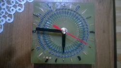
    You can also add a vertical partition to the horizontal barrier - the diffuser, which should improve the operation of the system even more. The photo of the solar tracker plate shows a blue accurate potentiometer. Please do not be influenced by this, it is a remnant of my attempts to connect the anemometer directly to the solar tracker system. Unfortunately it was not possible. The circuit according to the scheme after soldering should work properly. The width of the blind spot is regulated by the width of the diaphragm and the bending-bending of the LEDs working as sensors. (To the left of the L272, I won't change anything, on the right, maybe, yes. Isostat switches from old stocks were supposed to be used there.)
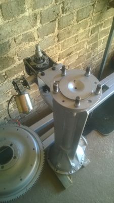
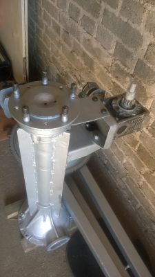
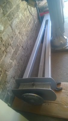
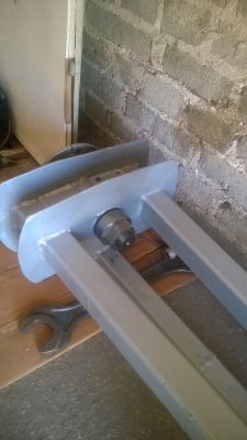
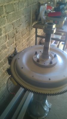
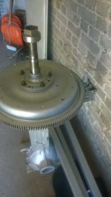
    The horizontal rotation of the panels is to be controlled by a system based on an analog clock. The return to the east is to be carried out in the morning using the twilight switch. The mechanical elements look like in the pictures for now. What you can see are the elements of the Żuk's rear bridge. Generally, I use recyclable materials to build my device.
    Simple solar tracker on the L272M for controlling solar panels.
    Simple solar tracker on the L272M for controlling solar panels. Simple solar tracker on the L272M for controlling solar panels. Simple solar tracker on the L272M for controlling solar panels. Simple solar tracker on the L272M for controlling solar panels. Simple solar tracker on the L272M for controlling solar panels. Simple solar tracker on the L272M for controlling solar panels.
  • #25 18025553
    gulon4
    Level 11  
    can you describe how you made the connection for the taper spline on the motor? which is what you are installing the rack on it :-)
  • #26 18025695
    heniek07
    Level 20  
    In the material fixed in the lathe chuck, first I drilled 3 holes, probably 6 mm, on the appropriate diameter, then rolled and cut the thread. I have a TUE 35, it has a wheel on the spindle of 96 teeth and I made a "dividing head" on it, I also have a new handle in which I attach the drill in a tool post. Two handles were created, because in the first one prepared for the worm gear, I changed the diameter for the shaft and used it for the engine. I did not plan to make a second handle to replace the rack. I was going to saw 3 lugs holding the rack and attach it to the weld at 3-4 points. Simple solar tracker on the L272M for controlling solar panels.
  • #27 18025868
    gulon4
    Level 11  
    and here is the dog buried, I do not have a lathe, I will use the original link from the poldek, it will be a complete set with the engine :-)
  • #28 18098388
    Pati
    Level 27  
    Hello! How do your rotating structures perform there? In winter, I am about to stir up something and I am thinking the most about the arrangement so that the center is a bearing and outside the wheel of the trolley, as one of my colleagues did here somewhere. I am thinking of a drive through the wheel and belt from a drum washing machine.

    I would like to do electronics with the homing system, but not the clock.

    4 collectors, 2m2 each for a 300l tank plus an additional tank in case of overheating.
  • #29 18098558
    SylwekK
    Level 32  
    In the event of overheating, you can always turn the collector in the other direction so that it does not heat up further. Of course, as soon as there is a driver and the entire turntable :)
  • #30 18105030
    gulon4
    Level 11  
    I welded a bit, I have the swivel mechanism, bearings and a few other necessary things, of course, in parts. The electronics have not been touched yet (complete lack of time), maybe in the fall I will move on with the topic because for now I have something else on my mind ;-) . When there is more time, I will send photos.

Topic summary

The discussion revolves around a solar tracker design utilizing the L272M operational amplifier for controlling solar panels. The system employs bright red LEDs for sunlight detection and has been tested with a wiper motor and H-bridge configurations using car relays. Participants highlight potential improvements, such as using phototransistors instead of LEDs for better sensitivity and addressing issues related to current surges and circuit protection. Various components, including MOSFETs and relays, are discussed for their roles in the control circuit. The conversation also touches on mechanical aspects of the tracker, including the installation of pinion shafts and the use of anemometers for wind protection. Users share their experiences and modifications, aiming for a more efficient solar tracking system.
Summary generated by the language model.
ADVERTISEMENT