logo elektroda
logo elektroda
X
logo elektroda

Broken cables at the Data logging stick slot (Solis Inverter)

tralalala81 9897 8
ADVERTISEMENT
Treść została przetłumaczona polish » english Zobacz oryginalną wersję tematu
  • #1 19058758
    tralalala81
    Level 2  
    Hello,

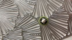
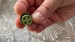
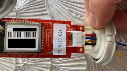
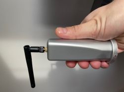
    The cable was broken during the installation of the Wi-Fi module to the Solis inverter, which resulted in connectivity problems some time after commissioning. I disassembled the module and it turned out that the cables are broken. Unfortunately, the last ones broke during disassembly. Do any of you have a diagram of connecting the module board to the socket and COM port? Does anyone know in what order these cables should be soldered to the plug with the markings (1,2,3,4). The following cables come out of the module:
    - VCC (red color)
    - B (blue)
    - A (yellow)
    - GND (black color)

    Attached are photos of my Wi-Fi module and socket ... Any help is appreciated. I would like to solder rather than buy a new one.

    Regards and thank you for your help !!!!
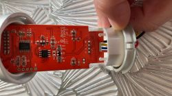

    Broken cables at the Data logging stick slot (Solis Inverter) Broken cables at the Data logging stick slot (Solis Inverter) Broken cables at the Data logging stick slot (Solis Inverter) Broken cables at the Data logging stick slot (Solis Inverter)
    Broken cables at the Data logging stick slot (Solis Inverter)
    I edited [TM]
  • ADVERTISEMENT
  • #2 19058797
    jdubowski
    Tube devices specialist
    It looks like a USB standard, you can determine VCC and GND with a voltmeter. The other two by trial and error.
  • ADVERTISEMENT
  • #3 19058819
    tralalala81
    Level 2  
    jdubowski wrote:
    It looks like a USB standard, you can determine VCC and GND with a voltmeter. The other two by trial and error.


    Yes, I thought it was USB, but won't the trial and error method burn the inverter or the device?
  • #4 19058919
    prose
    Level 35  
    Examine the output in the inverter where there is + and - and the rest of the test method, you will not burn anything if you connect + and- good.
  • ADVERTISEMENT
  • ADVERTISEMENT
  • #6 19060765
    tralalala81
    Level 2  
    pikulski wrote:
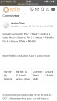
    Description in the attachment


    Many thanks !!!!!!! '
  • #7 19608802
    piowi
    Level 1  
    Hi. How can you write back to me when you connect these broken cables, i.e. what color to which pin number
  • #8 19608816
    rokbok
    Level 38  
    After all, you have been given above, post # 5.
  • #9 19894956
    serviscentrnadvira
    Level 1  
    1-red
    2- black
    3- yelow
    4 - blue

Topic summary

The discussion revolves around a user experiencing connectivity issues with a Solis inverter due to broken cables at the data logging stick slot after installing a Wi-Fi module. The user seeks assistance in identifying the correct wiring configuration for the module's cables, which include VCC (red), B (blue), A (yellow), and GND (black). Responses suggest using a voltmeter to determine VCC and GND, and to connect the remaining cables through trial and error, ensuring proper polarity to avoid damage. A diagram was provided, and a follow-up confirmed the correct pin assignments: 1-red, 2-black, 3-yellow, 4-blue.
Summary generated by the language model.
ADVERTISEMENT