logo elektroda
logo elektroda
X
logo elektroda

Understanding Star Wiring Diagram: Focal Point, Light Points, and Cable Connections

stirith 18708 14
ADVERTISEMENT
Treść została przetłumaczona polish » english Zobacz oryginalną wersję tematu
  • #1 19077968
    stirith
    Level 10  
    I would like to understand the star wiring diagram.

    I understand that the focal point is the switchboard and for example: I have a light point in the living room: I pull the cable (3x1.5) from this point to the switchboard. Then I pull the cable (3x1.5) from the switch box of this light point also to the switchboard and connect both cables. I connect the switch and nothing, because there is no current in this circuit ... to handle it, I have to pull a 3x1.5 cable with electricity from the switchgear to the switch? And if I have, for example, two points of light, of course, I repeat what I wrote above, but how with the "current" cable each time from the switchgear a separate cable with electricity for each switch separately? Can I pull the cable from switch to switch?

    greetings,
    Marcin
  • ADVERTISEMENT
  • #2 19077987
    adwlodar
    Level 28  
    stirith wrote:
    there is a switchboard

    If we talk about "device", "electrical cabinet", it is an electrical switchboard. The switchboard is a room. Unless that's what you meant.
    stirith wrote:
    I pull the cable (3x1.5) from this point to the switchboard.

    However, I recommend 4x1.5 or even 5x1.5
    stirith wrote:
    Then I pull the cable (3x1.5) from the switch box of this light point also to the switchboard and connect both cables.

    I also recommend 4x1.5 or 5x1.5
    stirith wrote:
    Can I pull the cable from switch to switch?

    You can do it just like in classic installation. Star installation only makes sense if you want to control the circuits in the switchgear in some sophisticated way. Or you just have such a whim. Just remember that then everything increases the cost, a larger switchgear, more apparatuses, some connectors for connections, etc. etc.

    You use the same cable as "power" the switch, then you also return to the switchboard. The only question is the number of wires: 3 or 4 or 5.
  • #3 19077992
    kkas12
    Level 43  
    Buddy, what are you writing about?
    Power, for example: you put the lighting circuit into the equipment box and from this box you lead the cable to the luminaire / luminaires and to the next equipment box in another (e.g. :) room.
    This "star" of yours concerns the power supply of individual circuits derived from the same fuse board and it is the opposite of the "ring" where the beginning and end of the circuit are located under the terminal of this protection.

    What you presented is nothing but CPR. Central distribution box.
  • #4 19078002
    stirith
    Level 10  
    For now, I'd like to understand the ideas of a star system. For me, switchgear = central connection point for all cables.

    But I still do not know whether I should supply the box each time with a separate cable with electricity from the switching station, or whether they can power from the can to the box - of course, keeping what I wrote earlier that one cable goes from the lighting point to the switchboard, the other from the box to the switchboard and this the third is "current" I do not know how to cover?
  • ADVERTISEMENT
  • #6 19078062
    stirith
    Level 10  
    adwlodar wrote:
    Okay, I understood that it was about building automation.

    Read: https://www.fachowyelektryk.pl/technologie/in...-hybrydowe-inteligentnego-domu-ohid-czesc-i-w Polsce.html


    A bit like that, but for now I want to make it work without any automation and in the future so that we can control all of them separately.
    In this article, they described it nicely - but there are KNX assumptions that I will definitely not have.

    Does anyone have any simple drawing of a star system? and how is it different from the aforementioned CPR?
  • #7 19078071
    adwlodar
    Level 28  
    stirith wrote:
    but there are KNX assumptions

    Put any other system in this place - it doesn't matter - I just gave you this to understand an idea.

    Anyway ... entering into google the password: "star electrical system" gives about 800 thousand results ... Let only 100 be adequate for you, then you have at least one week of acquiring knowledge. Ask for a detail later, because so far you are confusing a lot of things, I have an impression.

    PS YouTube doesn't bite either ...
  • #8 19078078
    kkas12
    Level 43  
    stirith wrote:
    ... one cable goes from the lighting point to the switching station, the second cable goes from the socket to the switching station and the third one is "current" I don't know how to cover it?
    Why do you need this "third current" if you want to lead the wires from the switch and the lamp wires to the fuse board.
    But explain the purpose of such a solution.
    stirith wrote:
    For me, switchgear = central connection point for all cables.
    Mistake. Certainly not all of them. This is just where all the circuits are powered from.

    Added after 1 [minutes]:

    stirith wrote:
    Does anyone have any simple drawing of a star system?

    So leave this "star" alone, because you don't interpret it that way.
  • ADVERTISEMENT
  • #9 19078147
    stirith
    Level 10  
    For me, this is a star below, but I'm probably wrong. I am asking for help, which is wrong. Because here the points of light go to the switching station - each separately. It is also shown here that the control of these light points is handled by automatics and a switch from automatics - I would like to replace it with ordinary switches for 230v.
    Understanding Star Wiring Diagram: Focal Point, Light Points, and Cable Connections


    Here it is like the article says "hybrid" but as I understand it is definitely not a star because the power supply goes from the light point to the switch, yes?
    Understanding Star Wiring Diagram: Focal Point, Light Points, and Cable Connections
  • #10 19078167
    kkas12
    Level 43  
    See what's written under the switchboard?
    You, on the other hand, wrote:

    stirith wrote:
    ... there are KNX assumptions that I will definitely not.


    And if you want to lead the power cables of the luminaires to the board and do the same with the cables from the switches, then lead them. Nobody will forbid you this, because who will jump to the rich?
    Just explain the purpose of this long-abandoned solution.
  • #11 19078193
    stirith
    Level 10  
    kkas12 wrote:
    See what's written under the switchboard?
    You, on the other hand, wrote:

    stirith wrote:
    ... there are KNX assumptions that I will definitely not.


    And if you want to lead the power cables of the luminaires to the board and do the same with the cables from the switches, then lead them. Nobody will forbid you this, because who will jump to the rich?
    Just explain the purpose of this long-abandoned solution.


    My goal is to understand how you can prepare an electrical installation that will initially be based only on a traditional electrical connection, but in the future will allow control by some automation system, e.g. Grenton.

    They write everywhere: The best for automation is a star topology, where each circuit (lamp, socket) is separately powered.

    And on the basis of the above statement, they try to figure out how these cables should be arranged correctly so that at the beginning I could connect "traditionally" and in the future some automation system. Of course, in my deliberations I did not write that in addition to the cans, I would like to pull some "twisted-pair" cables or other cables of this type to be able to handle this automation. At the very beginning I would like to understand this concept of a star and "powering each circuit (lamp, socket)" separately. That is why I wrote that since each circuit is powered separately, it probably goes from the lamp to the switchboard and from the box (switch) to the switchboard as well, and here I started to get tangled with this third "current" cable
  • Helpful post
    #12 19078208
    adwlodar
    Level 28  
    stirith wrote:
    by some automation system, e.g. Grenton.

    Did you forget to write about it in the first post?

    I don't know what else you need ... Do you expect knowledge, help and drawing with a ready project? Another material found in 5 seconds https://www.youtube.com/watch?v=q0IIerIuNlY

    Added after 2 [minutes]:

    stirith wrote:
    tangling with this third "current" cable

    WHAT 3 CABLE? Count the wires in the cable, e.g. 5x1.5.

    Draw for yourself how a simple circuit consisting of a connector for lighting and lamp works. First with the connections under the circuit breaker in the box, then just move these connections to the switchboard. You then get a star installation. Prepared for building automation, i.e. where the actuators are in the distribution board and where you have any control devices in the rooms: be it standard switches, touch panels or various crap ...
  • #13 19078239
    stirith
    Level 10  
    adwlodar wrote:
    stirith wrote:
    by some automation system, e.g. Grenton.

    Did you forget to write about it in the first post?

    I don't know what else you need ... Do you expect knowledge, help and drawing with a ready project? Another material found in 5 seconds https://www.youtube.com/watch?v=q0IIerIuNlY

    Added after 2 [minutes]:

    stirith wrote:
    tangling with this third "current" cable

    WHAT 3 CABLE? Count the wires in the cable, e.g. 5x1.5.

    Draw for yourself how a simple circuit consisting of a connector for lighting and lamp works. First with the connections under the circuit breaker in the box, then just move these connections to the switchboard. You then get a star installation. Prepared for building automation, i.e. where the actuators are in the distribution board and where you have any control devices in the rooms: be it standard switches, touch panels or various crap ...


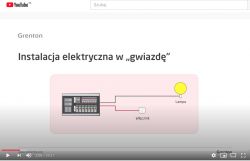
    So looking at this diagram from the presentation from the link you provided:
    Understanding Star Wiring Diagram: Focal Point, Light Points, and Cable Connections

    The cable goes from the lamp, e.g. 3.x.1.5 (brown, yellow, blue) to the switchboard, then I run the 4x1.5 cable (brown, black, yellow, blue) from the switch to the switchboard, connect the cables from the lamp with the switch cables (brown with brown, yellow with yellow and blue with blue), is left free black which I give the phase? - I fasten the black and brown switch in the box (using the switch) and when I turn it on, it will go from black to brown and the light will shine - I understand it correctly? what should I do with the yellow and blue cables that will be "slowly" left in the switch box?
  • ADVERTISEMENT
  • Helpful post
    #14 19078263
    adwlodar
    Level 28  
    stirith wrote:
    what should I do with the yellow and blue cables that will be "slowly" left in the switch box?

    You are about to leave them free. If you want to place a control module that requires an N conductor, you have an N conductor. When you install equipment in protection class 1, i.e. a lighting switch that requires a PE conductor, you have a PE conductor.

    Generally good now. You have the wire that goes from the connector (any phase colors):

    1 brown wire with voltage to the switch
    1 black wire with voltage behind the switch - already return - at the moment of closing
    1 blue netural vein
    1 PE protective conductor, yellow-green

    Just remember that when you want to have a double connector, the so-called candlestick, you need to use a 5x1.5 wire.
    The next question is where to use this (star) installation topology, and where to use the traditional one? It all depends on what, how and to what extent you want to control.
    In addition, an alternative version is to pass the lamp wire through the junction box - at a later stage, the control will probably be for some UTP type buses or something else, so you get one wire - he wrote about it kkas12
  • #15 19668157
    gilange
    Level 10  
    Good morning,
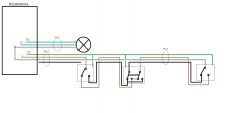
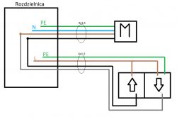
    I can see that the topic is not closed yet, so I will present my proposal for cabling lighting / roller shutters in a star topology. I don't want to buy a controller at the beginning and create logic - but I want to open the way to building automation in the future.

    I would not like the phase from the connector to appear on the blue wire and 4x1.5 cables with colors without blue I saw on the Allegro so there will be no problem with getting them. So I don't have to buy 5x1.5 to leave the blue wire (N) unused, unless someone below shows that it is needed.

    Below I present drawings of power supply solutions for devices from the above-mentioned assumption and please criticize my solution. During the operation of the installation, I would not be surprised that I did not anticipate something.


    Lighting

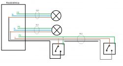
    Single switches - 2 switches can be connected with one 4x1.5
    Understanding Star Wiring Diagram: Focal Point, Light Points, and Cable Connections

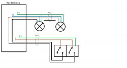
    Candlestick switch
    Understanding Star Wiring Diagram: Focal Point, Light Points, and Cable Connections

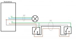
    Stair connectors
    Understanding Star Wiring Diagram: Focal Point, Light Points, and Cable Connections

    Cross connectors
    Understanding Star Wiring Diagram: Focal Point, Light Points, and Cable Connections

    Roller blinds
    Understanding Star Wiring Diagram: Focal Point, Light Points, and Cable Connections

Topic summary

The discussion revolves around understanding the star wiring diagram in electrical installations, particularly focusing on the configuration of light points and their connections to a switchboard. The star topology allows for individual circuits to be powered separately, facilitating future automation. Participants clarify that each light point should ideally have a dedicated cable running from the switchboard, and they discuss the appropriate cable types, such as 3x1.5 and 4x1.5. The conversation also touches on the necessity of neutral and protective conductors in the wiring setup, as well as the potential for future integration with automation systems. Various diagrams and examples are referenced to illustrate the concepts being discussed.
Summary generated by the language model.
ADVERTISEMENT