logo elektroda
logo elektroda
X
logo elektroda

Bosch 18V-40 Charger - Identifying Damaged PCB Components, Transistor W1A, Resistor Values

carl0s 15093 36
ADVERTISEMENT
Treść została przetłumaczona polish » english Zobacz oryginalną wersję tematu
  • #31 21358119
    yaro77
    Level 13  
    There was a suspect, also named
  • ADVERTISEMENT
  • #32 21418106
    pablo1521
    Oil burners specialist
    For posterity, foto's of the board and component markings.
    Electronic components on a circuit board, labeled as C9 and OC3. .
    Close-up of an electronic circuit board with visible components such as capacitors, diodes, and resistors labeled C2, D1, JP1, D3, R1, BR1. .
    Magnachip 80R9000Z electronic component mounted on a metal surface. .
    [img-3]
    Bosch Professional GAL 18V-40 charger with open case cover. .
    [img-5]
    [img-6].
    Close-up of a printed circuit board with electronic component labels. .

    Added after 10 [minutes]:


    A section of a green printed circuit board with visible electronic components such as resistors and diodes, labeled with numeric symbols. .
    Circuit board with labels and electronic components. .
    Close-up of a green printed circuit board with visible markings of electronic components. .
    Close-up of a printed circuit board with various component designations and test points. .
    Close-up of a green printed circuit board with electronic component markings. .

    Added after 4 [minutes]:


    Image of a green printed circuit board with component labels and test points. .
    Close-up of a printed circuit board with marked components and test points. .
    Image of a green printed circuit board with visible markings of components and vias. .

    Added after 3 [minutes]:


    Close-up view of electronic components labeled OC1 and OC2 on a circuit board. .

    Added after 6 [hours] 29 [minutes]:


    Close-up view of electronic components labeled OC1 and OC2 on a circuit board. .
  • ADVERTISEMENT
  • #33 21460370
    pacraf
    Level 16  
    Just so you know, I have the same fault as most, replacing the
    80R900P
    T2 = W1A
    R9 and R10 = 1 Ω
    and works normally.

    However, following advice found on YT, I soldered out one of the 4 resistors that (I think) are used to measure the charging current, which has the effect of reducing the charging current from 4 to 3A. Acctually in my case it was R51 that was soldered out, but this is irrelevant.

    I don't care about speed, I prefer to lower the power processed by the inverter and charge the battery more gently.

    Thank you for your contribution to this thread, the repair was a pleasure with such a source of information.

    Edit, I might just add that I bought the components on ALi, these 80R900P as "off the shelf" 5 pcs, I think there is less chance of some kind of fake. But this is my opinion only.
    Resistors the whole type set because I didn't have the big smd ones, and these tiny 20 pcs. W1 and everything fit in a dynasty of dollars....
  • #34 21506947
    kakaowiec1
    Level 10  
    Hello,
    Let me join the topic (same charger: GAL 18V-40).
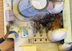
    In my case, the charger probably experienced a little flooding which caused a short circuit (at least that's what I infer from the marks on the board).
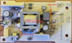
    Damaged GAL 18V-40 charger circuit board with visible signs of liquid damage. .

    Bridge area:
    Damaged circuit board of GAL 18V-40 charger with visible signs of short circuit and damage. .
    .
    After a light cleaning:
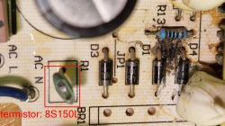
    Close-up of a damaged circuit board with a bridge rectifier and thermistor. .

    Damage found:
    - two of the four bridge diodes had a short circuit - replaced all. The resistor right next to them seems to have survived (brown, black, black, black, brown = 100om),
    - the 8S150L thermistor is damaged (you can see the chipping in the last photo)
    Other components appear to be ok.
    No visual/mechanical/thermal damage on the soldered side of the board.

    I have 3 questions for more experienced colleagues:
    1. the capacitor (400v/100uF) I don't have much to measure (the meter measures up to 20uF). Hooking up an ohmmeter to it causes it to indicate some value at first, which gradually increases until it indicates no resistance (so probably no short circuit in it). Is there any way to check it better without a meter with a suitable range?
    2) I cannot find the 8S150L thermistor in the shops. Is it possible to replace it with a substitute? (there is room in the housing, so cubically it could be something even noticeably larger).
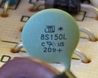
    Close-up of a green electronic component labeled 8S150L on a circuit board. .
    3. can the fuse (looks like a capacitor next to the brown power cable) be replaced with a normal tube fuse? (2,5A)
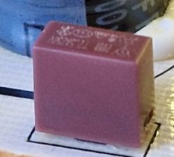
    Burgundy rectangular electronic component on a circuit board 2.
  • ADVERTISEMENT
  • ADVERTISEMENT
  • #36 21507120
    kakaowiec1
    Level 10  
    >>21507091 Thanks. This type should be able to be bought.
  • #37 21507293
    pablo1521
    Oil burners specialist
    Insert the fuse you have. As long as the amperage is the same.

Topic summary

The discussion centers on diagnosing and repairing a Bosch GAL 18V-40 battery charger that experienced severe damage, including a burnt PCB and housing. Key damaged components identified include the power transistor T2 (likely marked W1A or W04, often a PMBT3904 equivalent), resistors R9 and R10 (commonly 1Ω each, 1/4W, size 1206), the 80R900P MOSFET transistor (T1), bridge diodes, and thermistor 8S150L. The charger uses a flyback power supply topology with a programmed microcontroller. Repair efforts involve replacing these components, cleaning the PCB varnish, and testing with a series tungsten bulb to limit current during initial power-up. Additional components such as electrolytic capacitors (e.g., C4 at 1µF, non-electrolytic SMD type rated around 25-100V), optocouplers (OC1, OC2, OC3), and the MP6907GJ-Z integrated circuit on the secondary side are also discussed. Some users report successful repair by replacing T2 with W1A/PMBT3904, R9 and R10 with 1Ω resistors, and the 80R900P MOSFET, along with bridge diodes and thermistor. Issues such as AC voltage output on battery terminals suggest possible transformer or optocoupler faults. The role of optocouplers in feedback and MOSFET switching is analyzed. Some users mention modifying charging current by altering resistor R51. The discussion includes advice on component sourcing, PCB cleaning solvents, and preventive measures like improved MOSFET heat sinking. There is also a brief mention of converting a US 120V version to 240VAC by modifying bridge components and varistors.
Summary generated by the language model.
ADVERTISEMENT