FAQ
TL;DR: For EBL21 push‑pull, target Ra 9–10 kΩ (8 kΩ works). "very similar parameters to the 6V6." Build or repurpose an EL84/6AQ5 transformer, verify ECH21 inverter grid reference, and expect scarce OEM AGA specs. [Elektroda, aaanteka, post #19613947]
Why it matters: DIY tube‑amp builders get transformer specs, schematics, and inverter gotchas to finish EBL21 PP projects fast.
Quick Facts
- PP primary 9–10 kΩ recommended; 8 kΩ acceptable using EL84/6AQ5 iron [Elektroda, aaanteka, post #19613947]
- Original AGA “Special Version” output transformer data aren’t published; surviving radios are few [Elektroda, jozgo, post #19611656]
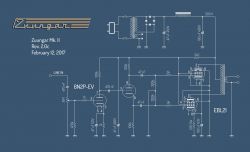
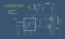
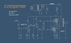
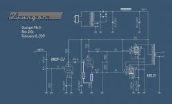
- Check ECH21 heptode grid (pin 7) reference in the phase inverter; some schematics omit polarity [Elektroda, W.P., post #19671088]
- Classic phase‑inverter variants are available for comparison before building [Elektroda, aksakal, post #19673129]
- Datasheet reference: ECH21 example inverter circuit (see page 18) [ECH21 datasheet]
What output transformer primary impedance should I use for EBL21 push‑pull?
Use a primary of 9–10 kΩ for standard push‑pull loads. An 8 kΩ primary also works when using EL84/6AQ5 transformers. This aligns with EBL21 behaving like a 6V6 class tube in PP service. Start with 9–10 kΩ for clean headroom, then evaluate. [Elektroda, aaanteka, post #19613947]
Can I reuse an EL84/6AQ5 push‑pull transformer with EBL21?
Yes. For less demanding builds, an EL84/6AQ5 PP transformer with about 8 kΩ primary works acceptably with EBL21 pairs. Expect slightly different loading and gain compared to 9–10 kΩ primaries. Check bias and balance after installation. [Elektroda, aaanteka, post #19613947]
Are EBL21 tubes close enough to 6V6 for PP designs?
Yes. As one expert notes, they have "very similar parameters to the 6V6." This lets you borrow many 6V6 PP design assumptions, especially transformer Ra values. Still verify screen voltage and bias specifics on your build. [Elektroda, aaanteka, post #19613947]
Where can I find a real‑world EBL21 push‑pull schematic to study?
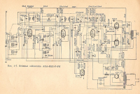
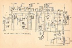
Look at the AGA Special Version radio reference shared in the thread. It points to a historical multi‑speaker set that used relevant topologies. Combine that with the posted thread schematics for guidance. [Elektroda, jozgo, post #19611590]
Do we know the specs of the original AGA output transformer?
No. Parameters weren’t documented publicly, and surviving units are rare. A member reports reviving one radio but confirms specs are unlikely to be found. Plan to design or select a modern PP transformer instead. [Elektroda, jozgo, post #19611656]
Which ECH21 pin is the heptode control grid in the inverter stage?
Pin 7 is the heptode control grid in this context. One shared schematic omitted its polarity, so double‑check your reference and add the required grid path. [Elektroda, W.P., post #19671088]
Do I need a grid‑leak or bias network on ECH21 pin 7?
Yes. Don’t leave the grid floating. Reference it with a leak or divider so the grid sits about 1–2 V below the cathode/midpoint. This stabilizes operating point and prevents drift. [Elektroda, jozgo, post #19672261]
What happens if the phase‑inverter grid is left floating?
A floating grid can wander, upsetting bias and stability. "The net cannot hang in the air"—add a grid resistor to define its potential and keep the stage predictable. This reduces noise and misbehavior. [Elektroda, jozgo, post #19672074]
Will the ECH21 datasheet phase‑inverter work as‑is?
Yes. A member compared the thread circuit to the datasheet and stated, "it will work as is." Use the datasheet’s reference as a baseline, then tweak component values for your tubes. [Elektroda, cirrostrato, post #19671910]
Where can I see classic phase‑inverter variants for comparison?
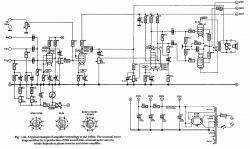
Two classic variants were posted for reference. Review them to choose a topology that matches your parts, transformer ratio, and desired gain balance. [Elektroda, aksakal, post #19673129]
How do I choose or adapt an output transformer for EBL21 push‑pull?
- Target a primary of 9–10 kΩ for a pair of EBL21.
- If repurposing iron, an 8 kΩ EL84/6AQ5 PP transformer is acceptable.
- Wire secondaries for your speaker load and confirm balance under signal.
[Elektroda, aaanteka, post #19613947]
Can the ECH21 heptode serve as a voltage amp with controllable gain?
Yes. In the posted build, the heptode section works as a voltage amplifier. The negative voltage at grid pin 6 is used for gain control because the tube is a selectode. [Elektroda, pawlik118, post #19673202]
Has anyone confirmed a working EBL21 push‑pull radio from this thread?
Yes. One member revived a rare AGA unit and reported success—“Works.” That confirms the viability of the shared topology and approach. [Elektroda, jozgo, post #19611656]
Is there a known error in one posted schematic here?
Yes. A reviewer noted the grid polarity for the ECH21 phase inverter (pin 7) was missing in diagram #5. Add the proper grid reference before powering up. [Elektroda, W.P., post #19671088]


