Elektroda.com
Elektroda.com
X

Universal starter boards for various SMD microcontrollers with a prototype area

p.kaczmarek2 2988 7
This content has been translated flag-pl » flag-en View the original version here.
  • Universal starter boards for various SMD microcontrollers with a prototype area
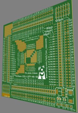
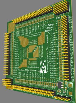
    I will present here a unique set of universal boards for SMT microcontrollers in cases like TQFP100, TQFP64 and TQFP48, various SSOP, SOIC, etc. filters, power block) and a large amount of free space for additional systems (prototyping zone).
    As part of the demonstration, I will setup a basic breakout for different microcontrollers, two made by Microchip and one by Silabs. In addition, I will present a few examples of peripherals for one of these microcontrollers, including EEPROM to I2C, USB to UART converter, ADC and a potentiometer, all to show how conveniently you can place the necessary elements and solder to the boards presented here.

    Jon Newcomb universal SMD breakout boards
    I got these plates as samples from Jon Newcomb to show them to the Electroda users. The boards can be purchased on the website below:
    https://www.ebay.com/usr/jon_newcomb?ul_noapp=true
    I also invite you to the author's website: http://www.jnewcomb.com
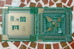
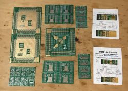
    Here are the available versions of the boards:
    Universal starter boards for various SMD microcontrollers with a prototype area
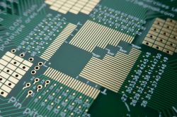
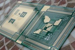
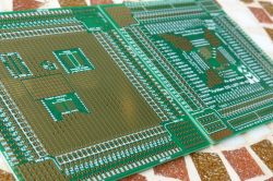
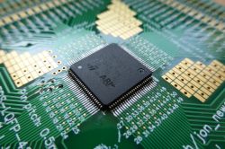
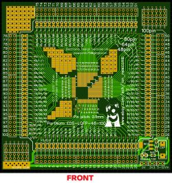
    Promotional graphics, on the example of the TQFP100 version:
    Universal starter boards for various SMD microcontrollers with a prototype area Universal starter boards for various SMD microcontrollers with a prototype area
    Universal starter boards for various SMD microcontrollers with a prototype area Universal starter boards for various SMD microcontrollers with a prototype area Universal starter boards for various SMD microcontrollers with a prototype area
    Universal starter boards for various SMD microcontrollers with a prototype area Universal starter boards for various SMD microcontrollers with a prototype area Universal starter boards for various SMD microcontrollers with a prototype area
    Universal starter boards for various SMD microcontrollers with a prototype area Universal starter boards for various SMD microcontrollers with a prototype area Universal starter boards for various SMD microcontrollers with a prototype area
    Universal starter boards for various SMD microcontrollers with a prototype area Universal starter boards for various SMD microcontrollers with a prototype area Universal starter boards for various SMD microcontrollers with a prototype area
    Universal starter boards for various SMD microcontrollers with a prototype area Universal starter boards for various SMD microcontrollers with a prototype area Universal starter boards for various SMD microcontrollers with a prototype area
    Universal starter boards for various SMD microcontrollers with a prototype area Universal starter boards for various SMD microcontrollers with a prototype area
    Versions are available:
    - VSSOP8, VSSOP10, VSSOP20, SSOP28, SOT-353 panel
    - QFP LQFP TQFP 48,64,100pin 0.5mm
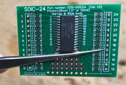
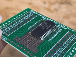
    - set of 4 - SOIC24 SOIC-24 (0.05 ", 50mil, 1.26mm)
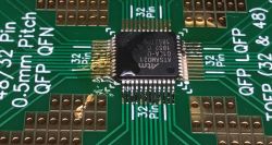
    - set of 2 - LQFP QFP TQFP QFN MLF 32/48 pin 0.5mm
    - set of 4 - SSOP24 0.635mm TSSOP MSOP
    - set of 4 - VSOP VSSOP MSOP QSOP MSSOP 0.5mm
    - a set of 4 pieces - SSOP SSOP24 0.65mm
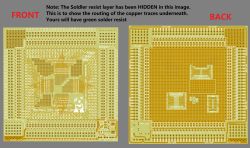
    These boards are distinguished by the fact that they have paths so that the power and ground connections to various pins are basically ready, all you need to do is put a tin jumper.
    Let's look at the TQFP 100 for example:
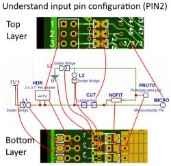
    Universal starter boards for various SMD microcontrollers with a prototype area
    Thanks to this, there are no problems with:
    - connecting the pin to ground
    - connecting the pin to the power supply
    - connecting a capacitor between the pin and ground or between the power supply and ground (for example VCAP from PICs)
    - connecting a filter on the pin input (e.g. analog, AVDD)
    - connecting a pull-up resistor for the pin
    - etc. etc.
    In addition, they offer ready places for the power section, programmer outputs and a large field for prototyping. The prototype fields are made in a thoughtful way, and in some boards (eg TQFP100) they also include pads for smaller chips in SOIC and SSOP. There is also room for the ETM-TRACE debugger in the TQFP.

    An additional example of the universality of jumpers
    But it is not everything. After re-examining the picture:
    Universal starter boards for various SMD microcontrollers with a prototype area
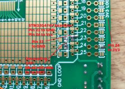
    you can even think of a way to conveniently connect the LED with a resistor on the GPIO of the microcontroller.
    1. Cross the "cuttable pad" from the diagram
    2. We solder the LED in its place
    3. We bridge L3
    4A. (if we want to ground) L3 is bridged, on L2 we solder the SMD resistor (say 330 ohms in 0805 housing) or axial on L2 / L3 pads with vias
    4B. (if we want to supply power) We solder the resistor on L1
    Ready! LED in place, no unnecessary wires and combinations.

    The kit I received
    Let's start with how the tiles look in practice. The first set I received:
    Universal starter boards for various SMD microcontrollers with a prototype area
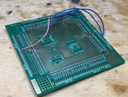
    This large TQFP100 board is the same three times in the picture, there is just a large prototype space on the bottom and descriptions of the role of the pins on the top, etc. their derivation.
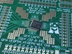
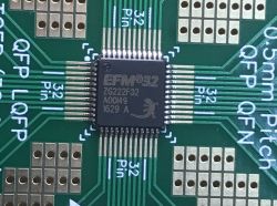
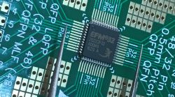
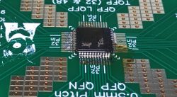
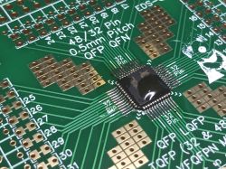
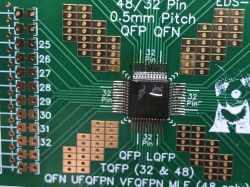
    The second set I got - 48 / 32pin 0.5mm QFP QFN:
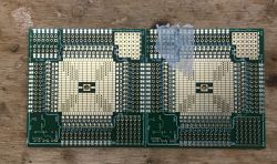
    Universal starter boards for various SMD microcontrollers with a prototype area Universal starter boards for various SMD microcontrollers with a prototype area
    At first glance, you can see that the tiles are of very good quality, but we will test them in practice anyway.

    Soldering equipment used
    For the demonstration of the board, I will use the most problematic soldering iron I have, i.e. a soldering iron, the tip of which I have not replaced since its purchase, additionally without power regulation.
    This is to demonstrate that you don't really need super hardware to run some microcontroller on these boards.
    Additionally, you have to forgive me for the poor quality of the solders, but I can see quite poorly and physically I am also not a master of coordination of movements.
    Here is my soldering kit used for this topic:
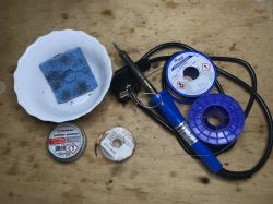
    Universal starter boards for various SMD microcontrollers with a prototype area
    We have here:
    - 30W silverline soldering iron
    - a sponge for cleaning the tip (I also have an ammonium chloride)
    - Sn60Pb40 solder binder (lead) in two versions, 1mm for THT and 0.25mm for SMD. I choose them because of their low melting point (lead-free to have a higher melting point)
    - soldering paste (how to make a bridge on the TQFP pins, then a bit of paste + movement along the pins / paths with the tip may save the situation)
    - braid for removing excess binder, including removing bridges on SMD pins as the paste method will fail
    In addition, I also have an IPA agent to remove the flux after soldering from the board. That's it - no soldering stations, no hot air, no temperature controls ... nothing like that. A beginner can easily run the TQFP-100 chip without such frills.

    TQFP 100 Demonstration - PIC32MZ2048EFG100
    It's time to demonstrate the use of this tile in practice.
    We will run PIC32MZ2048EFG100 on it - 32-bit microcontroller with 2MB flash memory and 512KB RAM.
    NOTE: There are different types of TQFP 100 - some have 0.4mm pin spacing, others 0.5mm. The 0.4mm version will not fit this board ... the 0.4mm version is called PIC32MZ2048EFG100-E / PT and the 0.5mm version is called PIC32MZ2048EFG100-I / PF.
    Anyway, everything is in his catalog note. We will need it:
    Universal starter boards for various SMD microcontrollers with a prototype area
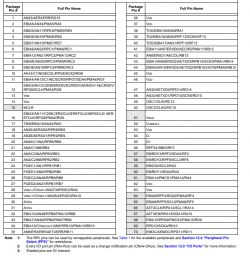
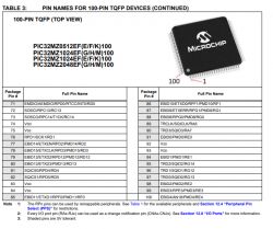
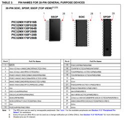
    You also need information about the findings:
    Universal starter boards for various SMD microcontrollers with a prototype area
    Universal starter boards for various SMD microcontrollers with a prototype area
    Universal starter boards for various SMD microcontrollers with a prototype area
    ATTENTION: Pin number 1 is the pin at the corner with a dot. The orientation of the text / graphics on the layout does not matter. It can sometimes be reversed. Adopting it may be misleading.
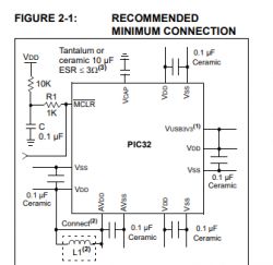
    Additionally, let's check what needs to be connected - section 2.1 Basic Connection Requirements :
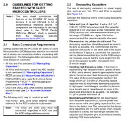
    Universal starter boards for various SMD microcontrollers with a prototype area
    We will stretch the rules a bit here, because decoupling capacitors should be " placed as close to pins as possible "(placed as close to the pins as possible) to minimize parasitic capacitance and inductance, and here is a bit of this gap, but I think it's acceptable for a learning breadboard.
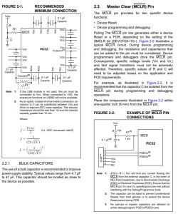
    Universal starter boards for various SMD microcontrollers with a prototype area
    Basically we have to do:
    - soldering the circuit to the board
    - jumpers for all VDD and GND pins (also AVDD and AGND)
    - decoupling capacitors 100nF for pins from the power supply
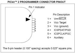
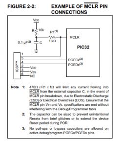
    - connection of the Pickit programmer via ICSP on MCLR / VDD / GND / PGD / PGC
    - LDO 3.3V with 5V input from USB (PIC32MZ requires 3.3V)
    Let's start by soldering the PIC. Positioning the system, I do it with antistatic tweezers but I do not touch its pins anyway, so as not to damage it with ESD, only the housing:
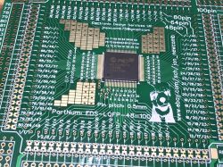
    Universal starter boards for various SMD microcontrollers with a prototype area Universal starter boards for various SMD microcontrollers with a prototype area
    Pin catching, I use 0.25mm lead tin, must also be flux:
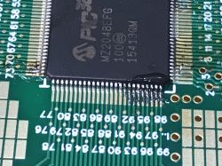
    Universal starter boards for various SMD microcontrollers with a prototype area
    Soldering; there were practically no short-circuits on the pins (but when there is a short-circuit, first I try to remove them with the soldering iron + paste, with movements along the pins, and if it does not go with a braid):
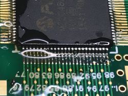
    Universal starter boards for various SMD microcontrollers with a prototype area
    Universal starter boards for various SMD microcontrollers with a prototype area Universal starter boards for various SMD microcontrollers with a prototype area
    After soldering, each pin must be checked, both for connection and for a short circuit with neighbors:
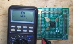
    Universal starter boards for various SMD microcontrollers with a prototype area
    Now all the VDD and GND pins need to be soldered.
    We have a download for this:
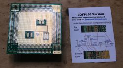
    Universal starter boards for various SMD microcontrollers with a prototype area
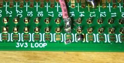
    Pin 14 is the power supply. Below is a jumper for VDD loop:
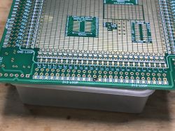
    Universal starter boards for various SMD microcontrollers with a prototype area
    Pin 13 is ground. Below the jumper to GND loop:
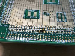
    Universal starter boards for various SMD microcontrollers with a prototype area
    After each jumper, we check whether we have made a short circuit to the power supply (or to the adjacent pins), because then when there is a short circuit, it will be more difficult to determine when it arose!
    Ready:
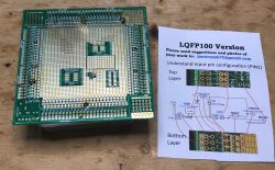
    Universal starter boards for various SMD microcontrollers with a prototype area
    Now we will do the power section.
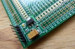
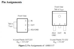
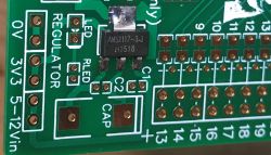
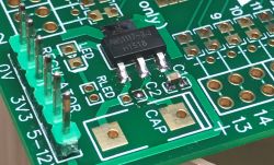
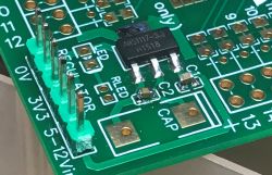
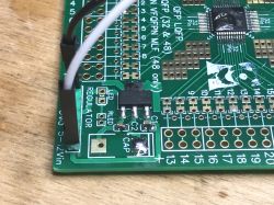
    You will need LDO - AMS 1117:
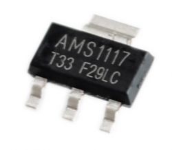
    Universal starter boards for various SMD microcontrollers with a prototype area
    Universal starter boards for various SMD microcontrollers with a prototype area
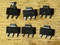
    Unfortunately I didn't have it in stock (I always use TC1264, MIC2940, etc). I had to find mine in the hatch:
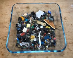
    Universal starter boards for various SMD microcontrollers with a prototype area
    Universal starter boards for various SMD microcontrollers with a prototype area
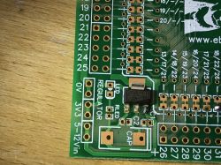
    I chose the 5EBL17-33. We can set it first and then solder it, and you can also first put the tin on one pad and then position it, while melting the tin:
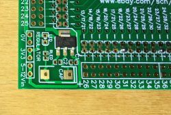
    Universal starter boards for various SMD microcontrollers with a prototype area Universal starter boards for various SMD microcontrollers with a prototype area
    In the meantime, you can also solder goldpins from the power supply:
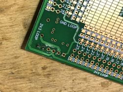
    Universal starter boards for various SMD microcontrollers with a prototype area
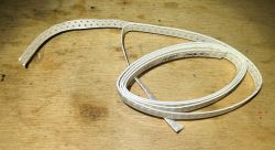
    Ready. Now let's prepare 100nF ceramic capacitors in 0603 housing. In total, one is already in the picture below - see?
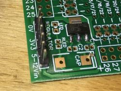
    Universal starter boards for various SMD microcontrollers with a prototype area
    They have no polarity.
    Universal starter boards for various SMD microcontrollers with a prototype area
    I solder them so that I tin one pad like this:
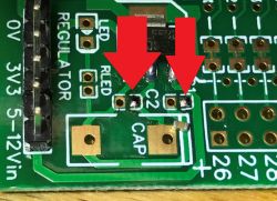
    Universal starter boards for various SMD microcontrollers with a prototype area
    I position the capacitor by melting the binder on that pad, then solder the other contact:
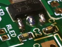
    Universal starter boards for various SMD microcontrollers with a prototype area
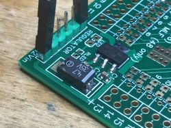
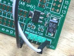
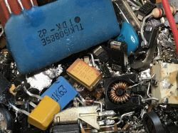
    Now it's time for the electrolytic capacitor. Those in SMD have a line where their + is. The capacitors at LDO are not just for show, they are necessary for its proper operation. I had to find my capacitor in the outlet:
    Universal starter boards for various SMD microcontrollers with a prototype area
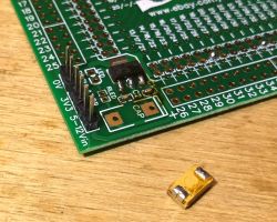
    Here, too, it may be more convenient to whiten one pad first, then warm it up, place the element, and then solder the other contact.
    Universal starter boards for various SMD microcontrollers with a prototype area
    Universal starter boards for various SMD microcontrollers with a prototype area
    Now decoupling capacitors for the VDD / GND pin pairs. Also at 100nF, such as before:
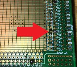
    Universal starter boards for various SMD microcontrollers with a prototype area
    The same for every couple.
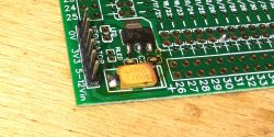
    Next in line is the programming connector, six-pin (basically a five-pin one is enough). The tile is so thought out that there is even a good place for it:
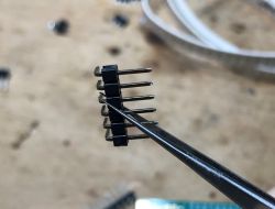
    Universal starter boards for various SMD microcontrollers with a prototype area
    Universal starter boards for various SMD microcontrollers with a prototype area
    Universal starter boards for various SMD microcontrollers with a prototype area
    Universal starter boards for various SMD microcontrollers with a prototype area
    I led the angular ICSP pins with the wires to the double goldpin strips, first these strips also had to be soldered:
    Universal starter boards for various SMD microcontrollers with a prototype area
    Universal starter boards for various SMD microcontrollers with a prototype area
    Universal starter boards for various SMD microcontrollers with a prototype area
    Universal starter boards for various SMD microcontrollers with a prototype area
    Time for a USB connector. It will make it easier to connect the 5V power supply to the input of the already installed 3.3V LDO:
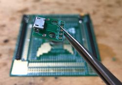
    Universal starter boards for various SMD microcontrollers with a prototype area
    Universal starter boards for various SMD microcontrollers with a prototype area Universal starter boards for various SMD microcontrollers with a prototype area
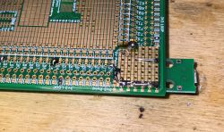
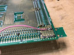
    The mass is easy to connect, 5V must be connected to the LDO by a cable:
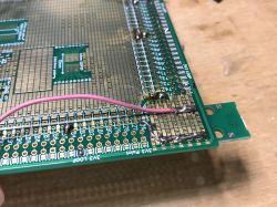
    Universal starter boards for various SMD microcontrollers with a prototype area
    Universal starter boards for various SMD microcontrollers with a prototype area
    The 10k resistor between MCLR and VDD has also been soldered (pull-up, forces the high state on the resetting pin):
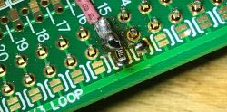
    Universal starter boards for various SMD microcontrollers with a prototype area Universal starter boards for various SMD microcontrollers with a prototype area
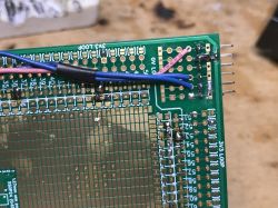
    (this cable goes from the ICSP connector to the MCLR, it's not the power supply).
    Basically that's it, all that's left to do is get the rest of the pins out. I decided to add one more LED, of course, with a resistor (also in the 0603 housing), with the goldpin output, so that I could connect it to any other pin with a female-female cable.
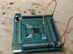
    Universal starter boards for various SMD microcontrollers with a prototype area
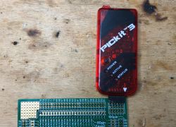
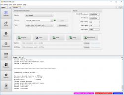
    PICKIT3 already allows you to program the PIC:
    Universal starter boards for various SMD microcontrollers with a prototype area
    You can upload blink led:
    Code: c
    Log in, to see the code

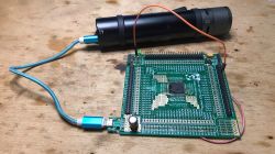
    The system works and the LED flashes, even when powered by a powerbank (flashlight):
    Universal starter boards for various SMD microcontrollers with a prototype area


    Additives for PIC
    These boards, however, allow much more than just starting a microcontroller.
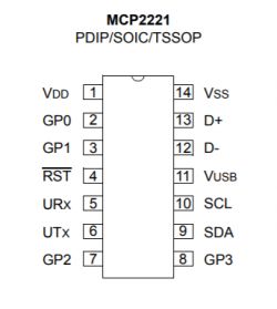
    You can also easily solder additional integrated circuits, e.g. the MCP2221 USB to UART converter:
    Universal starter boards for various SMD microcontrollers with a prototype area
    I chose the MCP2221 over the MCP2200 as the latter would require an external quartz resonator.
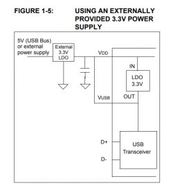
    The MCP2221 itself does not have big requirements:
    Universal starter boards for various SMD microcontrollers with a prototype area
    In addition, a 10k resistor on the RST pin (pull up), of course a 100nF capacitor for the power supply ...
    There is a place on the board just in time for this layout:
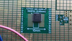
    Universal starter boards for various SMD microcontrollers with a prototype area
    We solder:
    Universal starter boards for various SMD microcontrollers with a prototype area
    Universal starter boards for various SMD microcontrollers with a prototype area
    Universal starter boards for various SMD microcontrollers with a prototype area
    Universal starter boards for various SMD microcontrollers with a prototype area
    I led RX / TX to these goldpins to be able to freely decide which PIC pins I will connect to MCP2221:
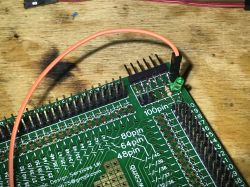
    Universal starter boards for various SMD microcontrollers with a prototype area
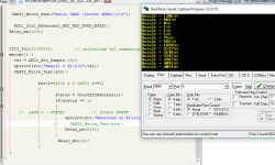
    Still need a test program ... you need to use PPS (Peripheral Pin Select) to select a pin to assign the role of TX output.
    Code: c
    Log in, to see the code

    UART works!
    Universal starter boards for various SMD microcontrollers with a prototype area


    Now we solder 24AA256, which is 256KBit EEPROM memory with I2C interface:
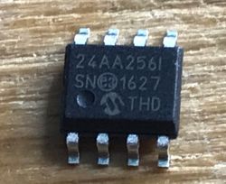
    Universal starter boards for various SMD microcontrollers with a prototype area
    Universal starter boards for various SMD microcontrollers with a prototype area
    Pins defining the address (A0, A1, A2) I will short circuit to ground for convenience. The WP status must also be low to disable the write lock.
    PIC32MZ has no I2C on PPS (Peripheral Pin Select), only on specific pins. But we have 5 different I2C modules to choose from. I chose I2C3:
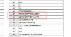
    Universal starter boards for various SMD microcontrollers with a prototype area
    We solder:
    Universal starter boards for various SMD microcontrollers with a prototype area
    Capacitor 100nF:
    Universal starter boards for various SMD microcontrollers with a prototype area
    SDA / SCL lines to PIC:
    Universal starter boards for various SMD microcontrollers with a prototype area
    More pull-up resistors for SDA / SCL lines:
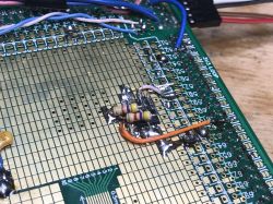
    Universal starter boards for various SMD microcontrollers with a prototype area
    It's time to check communication (at least initially):
    Code: c
    Log in, to see the code

    The PIC sees the I2C device with the address 160:
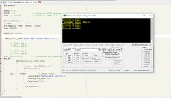
    Universal starter boards for various SMD microcontrollers with a prototype area

    Now maybe something more banal. Potentiometer, for ADC presentation. In the case of this board, there is a place for it, we solder it like we soldered the RESET button.
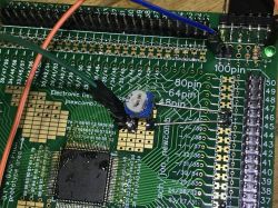
    Universal starter boards for various SMD microcontrollers with a prototype area Universal starter boards for various SMD microcontrollers with a prototype area
    These connections to pins 45/46 are of course ground and power connections. I put the potentiometer between the ground and the power supply, and its tap is the output of the voltage divider, and the ADC reads this voltage from it.
    Code:
    Code: c
    Log in, to see the code

    Result:
    Universal starter boards for various SMD microcontrollers with a prototype area
    The potentiometer works, as you can see on this PCB, you can do even quite a large project, and the prototype spot on top is also useful.

    TQFP48 Demonstration - EFM32ZG222F32
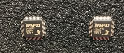
    Now it's time to present the second board based on a 32-bit Silabs microcontroller with the ARM Cortex-M0 + core:
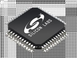
    Universal starter boards for various SMD microcontrollers with a prototype area
    Here, however, everything is the same as on the TQFP-100 version, so the commentary will be shorter.
    Here we also rely on the catalog note of the layout:
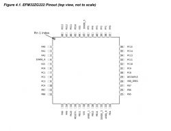
    Universal starter boards for various SMD microcontrollers with a prototype area
    The note must be read carefully - you must not forget, for example, about the necessary Decouple capacitor (in PICs it is called Vcap or Vusb):
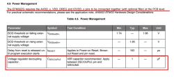
    Universal starter boards for various SMD microcontrollers with a prototype area
    We start soldering.
    Universal starter boards for various SMD microcontrollers with a prototype area
    Positioning:
    Universal starter boards for various SMD microcontrollers with a prototype area Universal starter boards for various SMD microcontrollers with a prototype area Universal starter boards for various SMD microcontrollers with a prototype area
    Here I tried to catch the chip with flux:
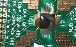
    Universal starter boards for various SMD microcontrollers with a prototype area
    Soldering:
    Universal starter boards for various SMD microcontrollers with a prototype area
    Universal starter boards for various SMD microcontrollers with a prototype area Universal starter boards for various SMD microcontrollers with a prototype area
    Power block. AMS1117. A bit of binder for the first pad ...
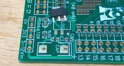
    Universal starter boards for various SMD microcontrollers with a prototype area Universal starter boards for various SMD microcontrollers with a prototype area
    Jumpers from GND and VDD Loop:
    Universal starter boards for various SMD microcontrollers with a prototype area Universal starter boards for various SMD microcontrollers with a prototype area
    DECOUPLE pin. A capacitor with a Cdecouple capacity, i.e. 1uF.
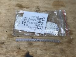
    Universal starter boards for various SMD microcontrollers with a prototype area
    Universal starter boards for various SMD microcontrollers with a prototype area Universal starter boards for various SMD microcontrollers with a prototype area Universal starter boards for various SMD microcontrollers with a prototype area
    Double rows of goldpins:
    Universal starter boards for various SMD microcontrollers with a prototype area

    100nF capacitors on input and output AMS1117:
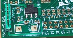
    Universal starter boards for various SMD microcontrollers with a prototype area
    Universal starter boards for various SMD microcontrollers with a prototype area Universal starter boards for various SMD microcontrollers with a prototype area
    4.7uF capacitor, also from the outlet:
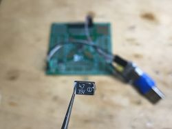
    Universal starter boards for various SMD microcontrollers with a prototype area
    Binder on the pad:
    Universal starter boards for various SMD microcontrollers with a prototype area
    Soldered:
    Universal starter boards for various SMD microcontrollers with a prototype area Universal starter boards for various SMD microcontrollers with a prototype area
    Ready chip for bootloader test:
    Universal starter boards for various SMD microcontrollers with a prototype area
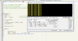
    The bootloader responds to the "U" character, i.e. EFM running:
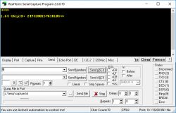
    Universal starter boards for various SMD microcontrollers with a prototype area
    I do not have the environment and compiler prepared for this system. In case of additional progress, I will complete the topic.


    Of course, this is how you can also run other microcontrollers ...
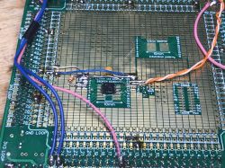
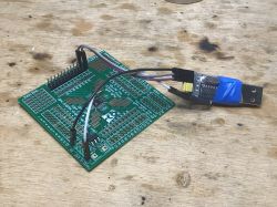
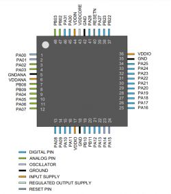
    For example, such ATSAMD21G18. I also started a trial with it, however it is not complete as my programmer for it is still on its way.
    This time just a few pics - everything as before.
    Universal starter boards for various SMD microcontrollers with a prototype area
    Universal starter boards for various SMD microcontrollers with a prototype area
    Universal starter boards for various SMD microcontrollers with a prototype area
    Universal starter boards for various SMD microcontrollers with a prototype area
    Universal starter boards for various SMD microcontrollers with a prototype area
    Universal starter boards for various SMD microcontrollers with a prototype area
    If I manage to start it, maybe I will do an ATSAM project on this board and also publish it on the forum.

    SOIC24 demonstration - what if we have a layout in SOIC28?
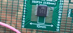
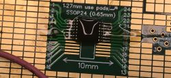
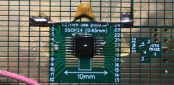
    You can really carve a lot on these tiles. Now I will present a SOIC24 board (pitch = 1.26mm) using PIC32MX150F128B in SOIC28.
    Yes, four pins will "hang" in the air, but thanks to the creativity of the tile's author, you can use them anyway:
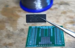
    Universal starter boards for various SMD microcontrollers with a prototype area
    Pinout:
    Universal starter boards for various SMD microcontrollers with a prototype area
    Connection required:
    Universal starter boards for various SMD microcontrollers with a prototype area
    Universal starter boards for various SMD microcontrollers with a prototype area
    First pin soldered:
    Universal starter boards for various SMD microcontrollers with a prototype area
    Next:
    Universal starter boards for various SMD microcontrollers with a prototype area
    Bending the extra-number pins (a simple trick to use the SOIC24 to SOIC28 plate). After soldering:
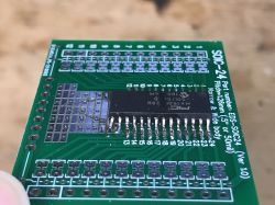
    Universal starter boards for various SMD microcontrollers with a prototype area
    Jumpers for ground on the bottom (no power loop here, we'll do it manually):
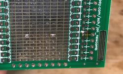
    Universal starter boards for various SMD microcontrollers with a prototype area
    VCAP capacitor (10uF, preferably tantalum, ESR

    Cool? Ranking DIY
    About Author
    p.kaczmarek2
    Moderator Smart Home
    Offline 
    p.kaczmarek2 wrote 4859 posts with rating 5193, helped 236 times. Been with us since 2014 year.
  • #2
    bobeer
    Level 28  
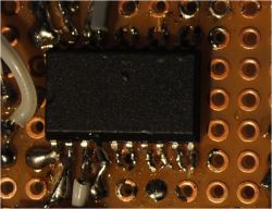
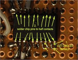
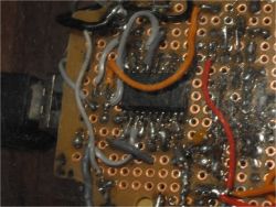
    The wide tqfp and tsop cases were soldered 10 years ago on a regular universal board (it was enough to cut the pads accordingly).
    I put the little qfn on my back once and made some extra legs, it also managed on the universal one.
    With 64 pin qf, I no longer have health for such fun and solder to the adapter ;)
  • #3
    p.kaczmarek2
    Moderator Smart Home
    bobeer wrote:
    The wide tqfp and tsop cases were soldered 10 years ago on a regular universal board (it was enough to cut the pads accordingly).

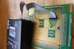
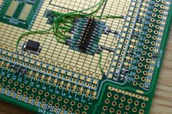
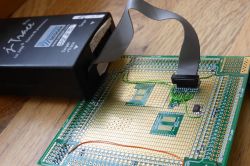
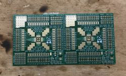
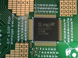
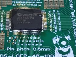
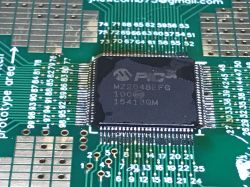
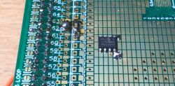
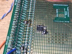
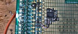
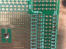
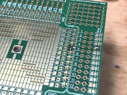
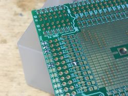
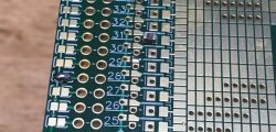
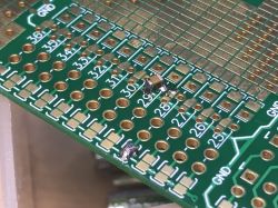
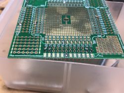
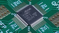
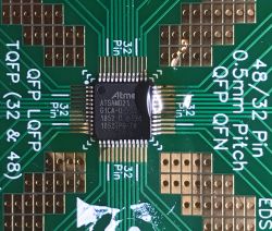
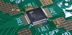
    I saw something like that on the Internet, I did not do it myself because, in my opinion, there are a bit too many combinations and I would be afraid that the pads will fall off if you accidentally use force or overheat. But I will attach photos (not mine!) That show what it looks like:
    Quote:

    Universal starter boards for various SMD microcontrollers with a prototype area
    Universal starter boards for various SMD microcontrollers with a prototype area
    Universal starter boards for various SMD microcontrollers with a prototype area
  • #4
    kowal011
    Level 21  
    Something fabulous!
  • #5
    romulus73
    Level 27  
    Strong, a lot of work invested.
  • #6
    SIEKIERA_666
    Level 21  
    Hi

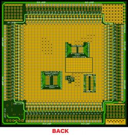
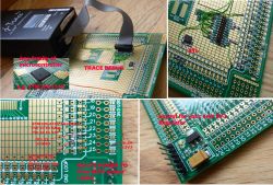
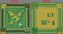
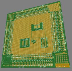
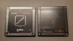
    It's a pity the article didn't appear sooner - before I ordered my first tiles from China.
    It would help me a little bit to design the prototype part.
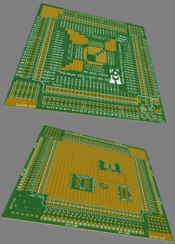
    The priority was to stuff the 240-legged boat.
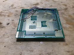
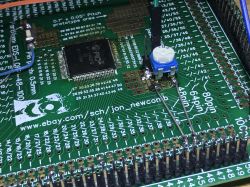
    Graphics and other elements added for "testing" purposes - what the producer can do ...

    Universal starter boards for various SMD microcontrollers with a prototype area
  • #7
    bobeer
    Level 28  
    Universal starter boards for various SMD microcontrollers with a prototype area

    I laughed :D

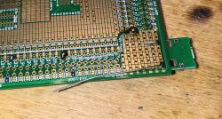
    Do you have too small holes for goldpins there?
  • #8
    SIEKIERA_666
    Level 21  
    With holes it is exactly as you say. I used the library modified by the "user" EasyEDA ... I enlarged the pads myself and did not check the holes.
    I do not intend to drill them in order not to lose the metallization - I will solder them to the butt.