Hi
I present a partial teardown and functional modification
OBD2 VGATE interface with a WiFi module instead of BT. This interface
I bought a few months ago and used in conjunction with the android
Head Unit in the car with the hybrid assistant app.
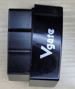
By default, the interface works as AP, creates an open WiFi network with SSID VLINK.
After connecting, the client device gets an IP address in the range 192.168.0.0/24.
The interface works as a transparent TCP bidirectional converter - serial, it listens to
address 192.168.0.10 and port 35000. On the ELM327 side, serial transmission 38400 bps.
You can connect to standard telnet and give commands to ELM327.
Elm327 presents itself as:
ATZ
ELM327 v2.1
ATI
OBDII is RS232 Interpreter
The interface takes up to 50mA when the WiFi module is working. You can
in it, turn off the automatic sleep mode after a preset time of inactivity.
After entering the sleep mode, the consumption drops to 1mA, but the module is already out of this mode
will not wake up because the WiFi interface is turned off. In addition, my copy is very tight
lowers the supply voltage, I will try to fight it because the ELM327 has the option of software calibration.
As the AP mode of the OBD2 interface is inconvenient for me, I decided to disassemble it
module in the hope that there will be ESP32 or something similar inside that will allow you to install it
alternative FW.
The module consists of 2 PCBs delicately connected for a sandwich:
- the lower one containing a complete OBD2 interface based on PIC18f25k80
- the upper one containing the HF LPT230 module and the 12V-> 3V3 converter. Conversion of voltages on the PIC18f25k80 line (5V supply)
is realized by a voltage divider
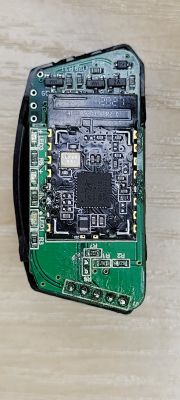
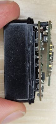
PCBs are connected with a 5-pin 2mm pitch connector, signals
LED ELM_RXD ELM_TXT GND 12V
The HF LPT230 module is a relatively popular and elegant solution
documentation is available at:
https://fccid.io/2ACSV-HF-LPT230/User-Manual/Users-Manual-3552381.pdf
For further experiments, I separated the RX and TX signals between
module a PIC18f25k80 and proceeded to further experiments with
UART - USB interface o terminal program and telnet. Among other things, I have verified
transparent data transmission.

Unfortunately, the attempt to access the default configuration page has failed
now the GUI shows up, but it asks for a password and the admin / admin documentation provided in the documentation does not work.

I tried the escape sequences described in the documentation: +++ waiting for the letter a and sending the character a
and it worked:
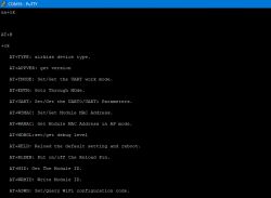
Using AT + commands changed the module configuration to STA, set
own SSID and encryption:
AT + WMODE = STA
+ approx
AT + WSSSID = Prius2
+ approx
and saved the configuration.
After rebooting, the OBD2 interface connected as a client, retrieved the IP address and was available in the HA in the car
head unit.
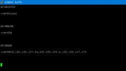
I achieved my goal relatively easily, but the module's response to escape sequences is ready
the product is a bit disturbing. Fortunately, the module only reacts from the serial interface side. Here I am reminded
from the beginning of the Internet adding +++ ATH0 in e-mails, which disconnected incorrectly configured TPSA modems.
I present a partial teardown and functional modification
OBD2 VGATE interface with a WiFi module instead of BT. This interface
I bought a few months ago and used in conjunction with the android
Head Unit in the car with the hybrid assistant app.

By default, the interface works as AP, creates an open WiFi network with SSID VLINK.
After connecting, the client device gets an IP address in the range 192.168.0.0/24.
The interface works as a transparent TCP bidirectional converter - serial, it listens to
address 192.168.0.10 and port 35000. On the ELM327 side, serial transmission 38400 bps.
You can connect to standard telnet and give commands to ELM327.
Elm327 presents itself as:
ATZ
ELM327 v2.1
ATI
OBDII is RS232 Interpreter
The interface takes up to 50mA when the WiFi module is working. You can
in it, turn off the automatic sleep mode after a preset time of inactivity.
After entering the sleep mode, the consumption drops to 1mA, but the module is already out of this mode
will not wake up because the WiFi interface is turned off. In addition, my copy is very tight
lowers the supply voltage, I will try to fight it because the ELM327 has the option of software calibration.
As the AP mode of the OBD2 interface is inconvenient for me, I decided to disassemble it
module in the hope that there will be ESP32 or something similar inside that will allow you to install it
alternative FW.
The module consists of 2 PCBs delicately connected for a sandwich:
- the lower one containing a complete OBD2 interface based on PIC18f25k80
- the upper one containing the HF LPT230 module and the 12V-> 3V3 converter. Conversion of voltages on the PIC18f25k80 line (5V supply)
is realized by a voltage divider


PCBs are connected with a 5-pin 2mm pitch connector, signals
LED ELM_RXD ELM_TXT GND 12V
The HF LPT230 module is a relatively popular and elegant solution
documentation is available at:
https://fccid.io/2ACSV-HF-LPT230/User-Manual/Users-Manual-3552381.pdf
For further experiments, I separated the RX and TX signals between
module a PIC18f25k80 and proceeded to further experiments with
UART - USB interface o terminal program and telnet. Among other things, I have verified
transparent data transmission.

Unfortunately, the attempt to access the default configuration page has failed
now the GUI shows up, but it asks for a password and the admin / admin documentation provided in the documentation does not work.

I tried the escape sequences described in the documentation: +++ waiting for the letter a and sending the character a
and it worked:

Using AT + commands changed the module configuration to STA, set
own SSID and encryption:
AT + WMODE = STA
+ approx
AT + WSSSID = Prius2
+ approx
and saved the configuration.
After rebooting, the OBD2 interface connected as a client, retrieved the IP address and was available in the HA in the car
head unit.

I achieved my goal relatively easily, but the module's response to escape sequences is ready
the product is a bit disturbing. Fortunately, the module only reacts from the serial interface side. Here I am reminded
from the beginning of the Internet adding +++ ATH0 in e-mails, which disconnected incorrectly configured TPSA modems.
Cool? Ranking DIY


