FAQ
TL;DR: Troubleshooting a dead Parkside PLG 20 A1? Expect 300–350 V on the bulk cap; "Is there about 300–350 V across the capacitor?" Use live checks, then inspect F1, SR4N60, optocoupler, and U1/IC1. [Elektroda, sigwa18, post #20641500]
Why it matters: For DIY owners of Parkside PLG 20 A1 chargers, this guide targets no-LED/no-charge faults and safe checks.
Quick Facts
- Live checks: verify 230 VAC at input and ~300–350 VDC across the largest primary capacitor. [Elektroda, sigwa18, post #20641500]
- Primary fuse F1 is 3.15 A; test continuity with the charger disconnected. [Elektroda, E8600, post #20468370]
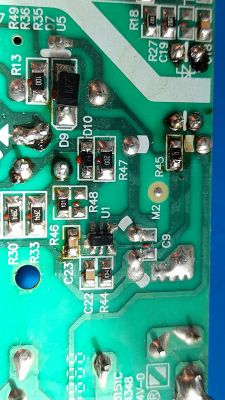
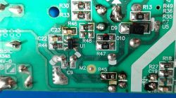
- Controller U1/IC1 (SOT23‑6, codes 30642/AAJ) was restored by replacing with SG6859ATZ. [Elektroda, piona5, post #21027120]
- Q3 MOSFET identified as NCE4953 with marking 1XKD5. [Elektroda, Matbar1132021, post #20864165]
- Primary zener rail measured 14.8 V in a working unit; no printed value on PCB. [Elektroda, oggy17, post #21078337]
How do I do first live checks on a dead PLG 20 A1?
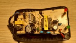
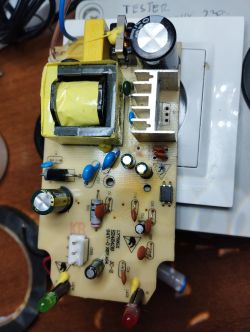
Use caution and take these measurements. 1. Confirm 230 VAC reaches the board input. 2. Measure around 300–350 VDC across the largest primary capacitor. 3. If missing, trace the input path and rectifier before the switcher. “Time for live measurements (CAUTION).” Expect 300–350 V on the bulk capacitor. [Elektroda, sigwa18, post #20641500]
Where is the fuse and how do I test it?
Locate F1 3.15 A on the primary side. Unplug the charger before testing. Set your multimeter to continuity and probe across F1. Replace if open. As one expert notes, take the “measurement with the charger disconnected.” [Elektroda, E8600, post #20468370]
LEDs still off but the fuse is fine—what next?
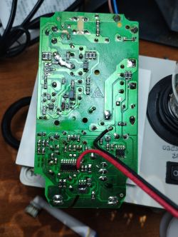
Check the main control transistor on the heatsink and the optocoupler. Inspect solder pads for cold joints and reflow suspect joints. Cold joints can mimic a dead supply and block startup. Focus on heat‑stressed parts and connectors. [Elektroda, E8600, post #20481403]
What is Q3 on the PLG 20 A1 board?
Q3 is identified as NCE4953, package code 1XKD5. Replace like‑for‑like and verify pinout and orientation. Clean pads before soldering. Test for shorts after installation. [Elektroda, Matbar1132021, post #20864165]
Which tiny 6‑pin controller is U1/IC1 (code 30642/AAJ), and what replacement works?
A user revived the charger by installing SG6859ATZ for the SOT23‑6 controller marked 30642/AAJ. The same chip also worked in a Vander VWA718 charger. “Also install SG6859ATZ :)” Confirm pinout and feedback connections. [Elektroda, piona5, post #21027120]
What output Schottky diode does this charger use?
One repair used an SB5200 on the secondary side, rated 200 V and 5 A. Test it for shorts out of circuit. Replace if shorted before powering the unit. Verify polarity during installation. [Elektroda, piona5, post #20976118]
What zener voltage should I expect on the primary reference rail?
A working charger measured 14.8 V across that zener. The PCB lacked a printed value. Use 14.8 V as your reference for checks. Replace only after confirming surrounding parts. [Elektroda, oggy17, post #21078337]
My red LED never turns green—where should I look?
Check Q5 and D4 in the regulation and indication path. One repair replaced Q5 and targeted D4 next. Confirm the 14.8 V zener rail is stable. Regulation faults can lock the LED state. [Elektroda, oggy17, post #21078337]
What primary MOSFET is used, and how do I test it?
Reported boards use an SR4N60 as the primary switch. With power removed, test for drain‑source shorts. If shorted, replace it and confirm gate resistors and snubbers before power‑up. [Elektroda, piona5, post #20976118]
How can I spot a failed switcher IC electrically?
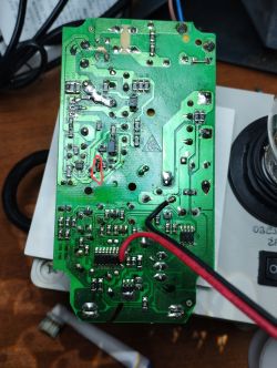
With the controller removed from load parts, check for internal pin shorts. A documented case showed pins 1 and 4 shorted even after lifting C23. That indicated a failed controller IC. [Elektroda, piona5, post #20976118]
What values are R21, R22, R23, and R24?
Users reported R21, R22, and R23 as 2 Ω each. R24’s value was not identified in‑thread. Match from an identical charger or a clear photo of the same PCB revision. [Elektroda, plichta, post #21604645]
Should I check the bridge rectifier early in diagnostics?
Yes. If you lack bulk DC, verify the input cable, fuse path, and the bridge rectifier block BR1 first. A contributor explicitly advised checking BR1 early. [Elektroda, sylwekbil123, post #21133771]
Is a series light‑bulb limiter useful for first power‑up?
Yes. One repairer powered the board through a bulb limiter during diagnostics. It helps limit fault current after part swaps. Use proper insulation and safe probing technique when testing. [Elektroda, sebcio1991, post #21048208]
Any confirmed success cases from this model in the thread?
Yes. Replacing the 6‑pin controller with SG6859ATZ restored a non‑starting charger. That report has guided similar fixes on comparable boards. [Elektroda, piona5, post #21027120]


 .
.