Hello everyone, this is my first time posting. I have an electrical background but this is not my expertise, so please bear with me.
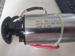
I have a KitchenAid Mixer (#4KSM6573CCU) that rated for 110VAC and I'm trying to convert it to work with 220VAC. This model is quite unique because it uses a DC Motor unlike the regular models.
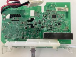
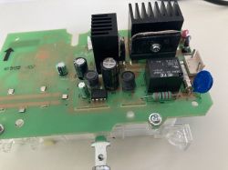
It has one board, the DC motor (120VDC, 2.1A), and a sensor (maybe a hall-effect). The board uses an LNK304PN to convert AC/DC for the MCU circuit which is good for 85-265VAC. From what I can see, they mostly built the PCB right out of the recommended PCB layout from the LNK304PN spec sheet.
For motor controls they use the bridge rectifier G2006-BP for the DC motor (preceded by a Triac T2050H-6T and Relay ORWH-SH-112HM3F) which also looks fine to me. I'll have to look again at the relay because the contacts are rated for 10A at 277VAC, but 15A at 125VAC.
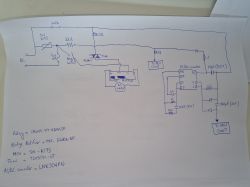
I traced the AC part of the PCB connections as best as I could (attached image), and from what I can see so far, I would need to replace the MOV (S14K175, 175A RMS), and a capacitor (22uF, rated 250V).
No worries if the board burns up in the process, I'm just doing this as a learning experience. Perhaps my next step would be to build something from scratch. I would really appreciate someone's help and advice on how to proceed. Thank you.


