logo elektroda
logo elektroda
X
logo elektroda

IGBT Module Issues at 15KW with 650V-700V DC Power Supply: Cause and Solutions

naxingyu29 756 2
ADVERTISEMENT
  • #1 20737797
    naxingyu29
    Level 1  

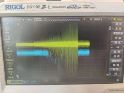
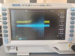
    We discovered a problem when building an inverter from DC to AC. When the IGBT module was working at 15 kW and the voltage of the DC power supply was 650V to 700V, the 5V and 3.3V power supply for the control chips fluctuated significantly, causing the chip to restart. We suspected that it might be caused by electromagnetic interference. We tried grounding, adding filters, and other measures but it didn't work. What is the possible cause and how to solve this problem? Digital oscilloscope displaying signal interference in waveforms. Oscilloscope displaying power supply interference.
  • ADVERTISEMENT
  • #2 20739007
    _lazor_
    Moderator of Designing
    I don't know anything about IGBT, so I'll give you some common potential problems and questions

    potential problems:

    - poor separation of the mass of the control part from the power part (I do not mean galvanic separation)


    questions:
    - How long are the wires in the control circuit?
    - What gate resistors?
    - what was the load?
    - how, how and in what places was the measurement made?
    - the magic ball has a malfunction, without a diagram I will seal blindly
  • #3 20739438
    mfac
    Level 17  

    If the attached oscillograms are meant to illustrate these fluctuations in the supply voltage, I suggest first checking the extent to which the voltage is actually disturbed and the extent to which its measurement using an oscilloscope is disturbed. All it takes is a loop that is too large between the probe and the ground crocodile, and we have a ready oscillogram like the ones shown. You also don't mention anything about PCB design, parasitic reactances in the system, etc. And what does it mean that you "tried grounding"? [Did it taste good? ;D]
ADVERTISEMENT