FAQ
TL;DR: "The reference for output current measurement is two or three parallel connected 0.05Ω constantan resistors!" Inspect these shunts and the feedback/control path before blaming the power module. [Elektroda, SQ5AZP, post #21694861]
Why it matters: This FAQ helps Minarc Evo 150 owners fix a "stuck at max amps" fault by targeting the actual current-control loop.
Quick Facts
- Symptom: display follows knob, but arc stays near full output (~140 A). [Elektroda, ftar, post #21693451]
- Likely cause: current-control/feedback circuit fault, not a dead IGBT module. [Elektroda, smd, post #21694512]
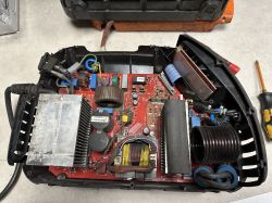
- Current sensing: two or three 0.05Ω shunts near the five TO‑247 output diodes; signal goes toward the panel corner via ribbon. [Elektroda, SQ5AZP, post #21694861]
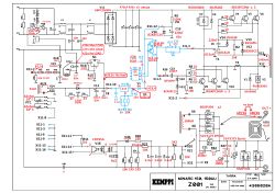
- No official EVO 150 schematic published; trace the board manually. [Elektroda, SQ5AZP, post #21694738]
- Quick wins: reseat all plugs/ribbon cables; inspect encoder/pot wiring and cold joints. [Elektroda, waldek63, post #21694587]
Why does my Minarc Evo 150 weld at full current even when set low?
Because the current-control loop isn’t modulating. The front panel accepts setpoints, but the feedback path that measures output current fails. When feedback is missing, the inverter drives hard and the arc stays at max. Focus on the shunt sense and panel/control traces. [Elektroda, smd, post #21694512]
Is the IGBT module the culprit if the welder still welds?
Unlikely. As one expert notes, if the module were faulty, the welder would not weld at all. A working arc with no regulation points to the current-control circuitry, not the switching module. "If the module was faulty, the welder would not weld at all." [Elektroda, smd, post #21694512]
Where is the current-sense hardware in the EVO 150?
Next to the output rectifier heat sink: look for two or three parallel 0.05Ω constantan shunt resistors near five TO‑247 diodes. Their signal routes to the board corner and across a ribbon toward isolation/amplifier and the control panel. [Elektroda, SQ5AZP, post #21694861]
What components commonly fail and cause a stuck‑max output?
Cracked or open resistors in the current-control path are a known failure. An intermittent or open shunt/trace makes the controller think current is low, so it drives maximum duty cycle. Inspect and meter every resistor in that path for drift and cracks. [Elektroda, smd, post #21694874]
How do I check the potentiometer/encoder side quickly?
First, reseat all panel and mainboard plugs. Then inspect the encoder/pot terminals and the panel PCB for cold joints or breaks. If an external test pot behaves the same, the fault is downstream in the control loop, not the knob. [Elektroda, waldek63, post #21694587]
Is there a schematic for the Kemppi Minarc EVO 150?
No official schematic has been published for the EVO 150. You will need to trace the board visually and follow the current-control paths from the shunts to the panel circuitry. [Elektroda, SQ5AZP, post #21694738]
What is PFC in this welder, and does it affect this fault?
PFC (power factor correction) is the front-end that shapes mains current; the EVO 150 has it. The stuck‑max symptom relates to the current-feedback/control loop, not PFC, so troubleshoot the shunts and control panel first. [Elektroda, SQ5AZP, post #21694861]
How does the EVO 150 power stage differ from older Minarc 150 units?
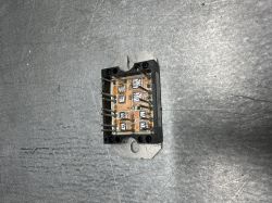
EVO 150 uses a dual‑forward amplifier on a 50 A module, while the older 150 uses six transistors in two groups. This affects layout and where you’ll find shunts and feedback routing when tracing faults. [Elektroda, SQ5AZP, post #21694861]
Where should I probe to confirm feedback reaching the panel?
Start at the shunt resistors, then follow the trace to the board corner and along the ribbon to isolation/amplifier into the control panel. Verify continuity and signal presence; repair any open joints or cracked parts you find. [Elektroda, smd, post #21694874]
What simple fixes should I try before replacing parts?
Do a connector and solder sanity pass. Reseat every plug and ribbon. Inspect and reflow suspicious joints on the encoder/pot and control panel. These restore many units with intermittent feedback faults. [Elektroda, waldek63, post #21694587]
Does a changing display mean the welder is fine?
No. The display can track your setpoint while the output ignores it. That mismatch signals a feedback/control failure: the setpoint updates, but the current-sense path does not inform regulation. [Elektroda, ftar, post #21693451]
What are the shunt resistor specs I should verify?
Expect two or three parallel shunts at about 0.05 Ω each. Measure low-ohms accurately and check for heat discoloration or fractures. Five TO‑247 rectifier diodes nearby help you locate the area. That’s your primary feedback source. [Elektroda, SQ5AZP, post #21694861]
Any numbers I can use to sanity‑check the hardware layout?
Yes. Look for five output rectifier diodes in TO‑247 packages and 2–3 constantan shunts in parallel (0.05 Ω each). If those counts differ, suspect prior repairs or missing parts. [Elektroda, SQ5AZP, post #21694861]
Quick how‑to: basic diagnostic workflow for this fault?
- Power off, discharge caps, and photograph the board for reference.
- Reseat all plugs/ribbons; inspect and reflow panel and shunt‑path joints.
- Ohm/trace from shunts to the panel control input; replace any cracked/open resistors.
[Elektroda, smd, post #21694874]
 - but it only welds on full current (140a) no matter what I set it to. Any advice where to start looking? What is controlling current output?
  - but it only welds on full current (140a) no matter what I set it to. Any advice where to start looking? What is controlling current output?


