 .
.
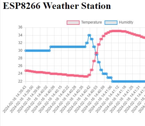
I invite you to the second part of the adventure with the Wemos D1 ESP8266 board and the DHT11 temperature/humidity sensor. In this part I will expand my program to write the results to the Flash memory of the ESP8226, I will use a library with the graceful name EEPROM . Why is the class for writing to Flash called here EEPROM ? Let's find out!
Previous topic in the series:
Wemos D1 "Arduino" and DHT11 - a simple weather station with graphs on the web .
We're about to start, but first...
Flash memory usage warning .
In this topic I present the recording of results in Flash memory. It's simple and accessible, so as tempting as possible, but it can also be deceptive. Flash memory gets used up quite quickly due to the erase cycles performed.
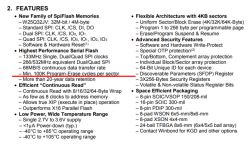
Let's assume that our module with ESP8266 has W25Q32 memory on board, this is the memory connected to it via SPI, in this memory our program is stored, but we can also write measurements there.... however, this memory has some limitations. The datasheet says one line about them, sewn into a lot of other information:
 .
.
100,000 erase cycles per sector.... assuming the worst case scenario that we write measurements to one sector, and assuming that each write is preceded by an erase, then we have 100 000 measurement write events.
100 000 measurements, how many is that? Let's assume one measurement per hour.
100000/24 is about 4166 days. That is about 11 years...
Not likely to be a very good result if we want to create something more than a simple program to play with. And with e.g. 10 times the recording frequency we already drop to 1 year.... (minimum).
However, I will solve this problem in the third part, for now let's try to skip it and just learn the simplest way to write to Flash .
Here we go. As a reminder, I am posting the code from the previous topic:
Code: C / C++
Memory "EEPROM" .
The ESP8266 does not have an EEPROM, but someone came up with the idea of emulating it via Flash memory. To start with, we can try to use this. It's not a very good idea, because frequent writing will consume our precious flash erase cycles, so we have to avoid writing too often, but as an exercise we can try to do it anyway.
So we include the header:
Code: C / C++
As luck would have it, all the documentation is here:
https://arduino-esp8266.readthedocs.io/en/latest/libraries.html
There is also a warning about rapid flash consumption in the documentation:
Quote:..
Note that the sector needs to be re-flashed every time the changed EEPROM data needs to be saved, thus will wear out the flash memory very quickly even if small amounts of data are written. Consider using one of the EEPROM libraries mentioned down below.
It is also worth seeing the source code of the library used:
https://github.com/esp8266/Arduino/blob/master/libraries/EEPROM/EEPROM.cpp
For writing and reading we have the template functions put and get , which do everything for us. In addition you need to start the EEPROM with the function begin :
Code: C / C++
In place of x we insert the size of the EEPROM to be used.
The EEPROM here can be up to 4096 in size, so you need to count how much space what will take up. Our structure is, recall:
Code: C / C++
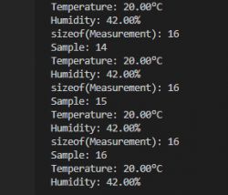
This has 16 bytes with us, by the way, let's check, sizeof the truth will tell us:
Code: C / C++
16 bytes:
 .
.
Since this is the case, this structure will fit a whole 256 times in 4096, but we still want to be able to store the index of the last measurement, so let's assume we will store 255 samples:
Code: C / C++
So we implement, first - read:
Code: C / C++
At position 0 in memory, there will be an integer - the index of the last sample from the circular buffer, followed by the samples in sequence.
Now the notation:
Code: C / C++
The record still needs to be called commit to make a proper record of the changes.
It remains to be seen whether this works. For this purpose I have additionally given a display to the console of the index of the last sample:
Code: C / C++
We upload and observe the changes in the console:
 .
.
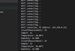
When the board is restarted, will the sample countdown resume from the saved index?
 .
.
Yes, it looks like the save works .
But wait a minute...
The graph does not display! .
We get an error in the console:
 .
.
We execute "Examine Source" on the page to see what went wrong:
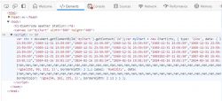 .
.
We have a bunch of values in memory nan , meaning "not a number". This needs to be fixed.
Protect against junk in memory .
Our The problem stems from the fact that the current version of the code naively loads from memory what is there, without any verification of this data. And after all, this system has only just been developed and we don't know what is in that memory, the values there could be quite undefined.
It would be possible to just manually clear this memory once and set the zeros there alone, but you could also manage a bit more cleverly. Just use the checksum .
A checksum is a special value which is calculated from more data in memory. The checksum function is designed so that a small change in the data results in an immediate change in the result of this sum. Thus, if we calculate the checksum for an array and flip even one bit in that array, the checksum should already have changed. Of course, this is not an ideal solution, as there are so-called collisions, but for this application, let me ignore that....
A popular checksum system is CRC32. Just right for 4 bytes, 32 bits, we also have a library ready for it:
 .
.
Example from the author of the library:
Code: C / C++
We need to count the checksum of the entire data block each time it is written, and write it then to the EEPROM:
Code: C / C++
For simplicity I don't count the checksum for the index of the last sample either, but in general I should do that too.
As of now, my memory structure is as follows:
- offset 0 - last sample (integer, 4 bytes)
- offset 4 - crc32 checksum (integer, 4 bytes)
- offset 8 - measurement data
At program start, when reading samples, we have to read the "old" checksum and count the same for the loaded data. We then compare these values and if they are the same, we assume that no unwanted change has occurred. If they are different, then surely something has gone wrong or there were no samples in memory:
Code: C / C++
If we already know that there is no valid data in memory, we also need to manually clear that memory, count the correct checksum and write that data to it:
Code: C / C++
It is time to test the mechanism developed. At this point there are unexpected values in memory, so we will expect a bad checksum message once, and then with each reboot of the board this checksum should be fine.
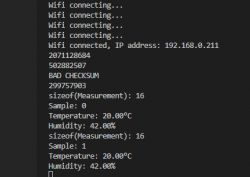 .
.
After pressing RESET:
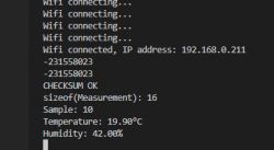 .
.
Indeed, on the second reading the checksum was already correct. The system works:
 .
.
The measurement values are properly remembered, even after the power supply to the device is lost.
Summary .
In this section we learned about the EEPROM class which in this release provides access to... Flash memory and we organised a working but not very efficient write of data to this class. By the way, we practised topics such as checksum, etc.
The developed system works, but is not suitable for frequent writing of results. Still, if we had used the EEPROM to save some settings (e.g.. WiFi passwords, only when they are changed by the user) then this would be better, but for frequent writes this is not suitable.
For this reason in the third part I will rewrite this program and optimise it to reduce Flash memory usage. We'll see (and count) how many times I can extend the estimated lifetime of our poor sectors.
Of course, you could also just use an external EEPROM.... the code would be easy to flip on that. Let's look to the datasheet note of some EEPROM how many cycles it will last. For example the 24LC256:
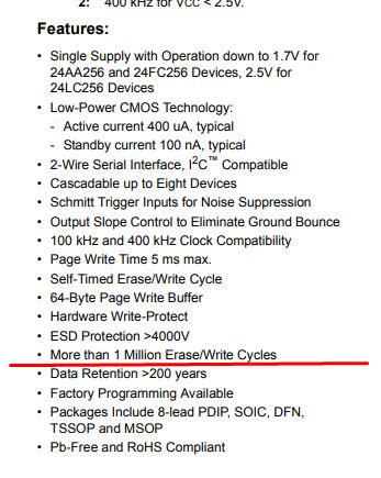 .
.
So far - that's it. Feel free to share your own experiences with the subject under discussion, how would you organise the storage of these measurements?
Cool? Ranking DIY Helpful post? Buy me a coffee.


