logo elektroda
logo elektroda
X
logo elektroda

How to connect M5 Dual Kmeter 13.2 module to ESP32S3 via I2C? The module is not detected

Belialek 204 5
ADVERTISEMENT
Treść została przetłumaczona polish » english Zobacz oryginalną wersję tematu
  • #1 21182303
    Belialek
    Level 22  
    Hello!

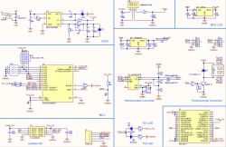
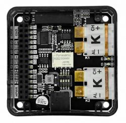
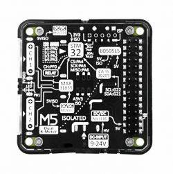
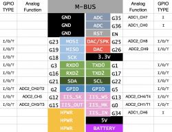
    I'm having trouble connecting the M5 Dual Kmeter 13.2 module to the ESP32S3. According to the documentation, this module has a built-in STM32 that allows communication via I2C, which as far as I understand is brought out on pins 21 and 22. I connect the power supply (the LED on the module lights up), SDA/SCL to the ESP32 pins and unfortunately the module is not detected by the simple scanner in the Arduino IDE. Another module, which also communicates via I2C, is detected without any problems when connected.

    What could I be doing wrong?
    How to connect M5 Dual Kmeter 13.2 module to ESP32S3 via I2C? The module is not detected .
    How to connect M5 Dual Kmeter 13.2 module to ESP32S3 via I2C? The module is not detected .
    How to connect M5 Dual Kmeter 13.2 module to ESP32S3 via I2C? The module is not detected .
    How to connect M5 Dual Kmeter 13.2 module to ESP32S3 via I2C? The module is not detected .

    Code: Arduino
    Log in, to see the code
    .
  • ADVERTISEMENT
  • #2 21182803
    ex-or
    Level 28  
    The most obvious mistake you could have made is the lack of pull-up resistors. You could also have not done it but that, apart from you, only the fairy knows.
  • ADVERTISEMENT
  • #3 21184551
    Belialek
    Level 22  
    Actually, I hadn't even thought of that - I always connected I2C directly and it always worked. What values are best to use, and are they on both communication pins?
  • ADVERTISEMENT
  • #4 21184799
    ex-or
    Level 28  
    It has always worked... One module has resistors, another does not. When you always connect the former it always works, when you connect the latter it never works, and when you connect different ones on the same bus it varies. The resistors must be on both lines and their value is in principle calculated. In practice I don't think anyone does this and for a 3.3V supply something between 3 and 5k is assumed.
  • ADVERTISEMENT
  • #5 21185509
    Belialek
    Level 22  
    I have connected the SDA and SCL to the 4.7K resistors, with which I pulled up 3.3V to the GPIO inputs on the ESP32. I still cannot detect this module.
  • #6 21186507
    khoam
    Level 42  
    Belialek wrote:
    What could I be doing wrong?
    .
    In the code posted in the first post, are you treating the value 0 returned by Wire.endTransmission () as an error? If so, this is an error.

    Generally Wire.endTransmission () may return the following values:

    0: success.
    1: data too long to fit in transmit buffer.
    2: received NACK on transmit of address.
    3: received NACK on transmit of data.
    4: other error.
    5: timeout
ADVERTISEMENT