Hello,
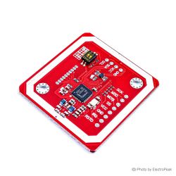
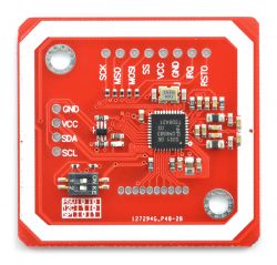
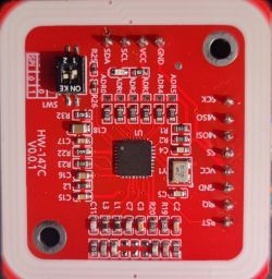
I have a PN532 RFID reader
 .
.
I have used it before, connecting it to an Arduino Nano. Now I have switched to ESP32, specifically ESP32-S3-WROOM-1, and a problem arises. In I2C mode, the scanner detects the reader, but in no way am I able to read any tag. Example program on I2C:
.
After switching to SPI, zero communication, example program:
.
But interestingly leaving exactly the same pins and changing the reader to RC522 everything works without any problem, code for RC522:
.
I found several threads on Reddit on this subject, but none of these solutions helped.
I have a PN532 RFID reader
 .
.
I have used it before, connecting it to an Arduino Nano. Now I have switched to ESP32, specifically ESP32-S3-WROOM-1, and a problem arises. In I2C mode, the scanner detects the reader, but in no way am I able to read any tag. Example program on I2C:
#include <Wire.h>
#include <Adafruit_PN532.h>

// Definiujemy piny I2C dla ESP32-S3
#define SDA_PIN 12
#define SCL_PIN 13

// Definiujemy piny IRQ i RESET (jeśli nie podłączone, zostaw -1)
#define IRQ_PIN -1
#define RESET_PIN -1

// Inicjalizacja PN532 przez I2C
Adafruit_PN532 nfc(IRQ_PIN, RESET_PIN);

void setup() {
    Serial.begin(115200);
    while (!Serial) delay(10); // Czekaj na otwarcie portu szeregowego

    Serial.println("Inicjalizacja PN532 (I2C)...");

    // Inicjalizacja I2C na ESP32-S3
    Wire.begin(SDA_PIN, SCL_PIN);
    Wire.setClock(100000);  // Ustawienie prędkości I2C na 100 kHz

    // Opóźnienie na stabilizację
    delay(100);

    // Inicjalizacja PN532
    nfc.begin();

    // Sprawdzenie komunikacji z PN532
    uint32_t versiondata = nfc.getFirmwareVersion();
    if (!versiondata) {
        Serial.println(" Błąd: NIE WYKRYTO PN532 przez I2C!");
        Serial.println(" Sprawdź połączenia SDA/SCL i tryb pracy modułu.");
        while (1);  // Zatrzymujemy program
    }

    Serial.print(" PN532 wykryty! Wersja firmware: 0x");
    Serial.println((versiondata >> 24) & 0xFF, HEX);
    Serial.print("Firmware ver. ");
    Serial.print((versiondata >> 16) & 0xFF, DEC);
    Serial.print('.');
    Serial.println((versiondata >> 8) & 0xFF, DEC);

    // Ustawienie czytnika w tryb odczytu kart NFC
    nfc.SAMConfig();
    Serial.println(" PN532 gotowy! Przyłóż kartę NFC...");
}

void loop() {
    uint8_t uid[7];  // Tablica na UID karty
    uint8_t uidLength;

    Serial.println(" Czekam na kartę...");

    // Sprawdzenie, czy karta jest w zasięgu
    if (nfc.readPassiveTargetID(PN532_MIFARE_ISO14443A, uid, &uidLength)) {
        Serial.println(" Karta wykryta!");

        Serial.print("  UID Length: ");
        Serial.print(uidLength, DEC);
        Serial.println(" bytes");

        Serial.print("  UID Value: ");
        for (uint8_t i = 0; i < uidLength; i++) {
            Serial.print(uid[i], HEX);
            Serial.print(" ");
        }
        Serial.println("\n");

        delay(2000);  // Poczekaj przed kolejnym odczytem
    } else {
        Serial.println(" Brak karty w zasięgu.");
    }

    delay(500);  // Krótkie opóźnienie przed kolejnym sprawdzeniem
}
After switching to SPI, zero communication, example program:
#include <SPI.h>
#include <Adafruit_PN532.h>

// Definiujemy piny SPI dla ESP32-S3
#define SS_PIN 42   // Chip Select (CS) – Możesz zmienić
#define SCK_PIN 12
#define MISO_PIN 13
#define MOSI_PIN 11

// Tworzymy obiekt PN532 dla SPI
Adafruit_PN532 nfc(SS_PIN, &SPI);

void setup() {
    Serial.begin(115200);
    Serial.println("Inicjalizacja PN532 (SPI)...");

    // Inicjalizacja SPI z wymuszeniem pinów
    SPI.begin(SCK_PIN, MISO_PIN, MOSI_PIN, SS_PIN);
    SPI.beginTransaction(SPISettings(100000, MSBFIRST, SPI_MODE0)); // Zmniejszona prędkość SPI

    // Inicjalizacja czytnika PN532
    nfc.begin();

    uint32_t versiondata = nfc.getFirmwareVersion();
    if (!versiondata) {
        Serial.println("Błąd: NIE WYKRYTO PN532 przez SPI!");
        Serial.println("Sprawdź połączenia i tryb SPI.");
        while (1);  // Zatrzymujemy program
    }

    Serial.print("PN532 wykryty! Wersja firmware: 0x");
    Serial.println((versiondata >> 16) & 0xFF, HEX);

    // Ustawienie czytnika w tryb odczytu NFC
    nfc.SAMConfig();
    Serial.println("PN532 gotowy! Przyłóż kartę NFC...");
}

void loop() {
    uint8_t uid[7];  // UID karty
    uint8_t uidLength;

    Serial.println("Czekam na kartę...");

    // Sprawdzenie obecności karty
    if (nfc.readPassiveTargetID(PN532_MIFARE_ISO14443A, uid, &uidLength)) {
        Serial.println("Karta wykryta!");

        Serial.print("  UID Length: ");
        Serial.print(uidLength, DEC);
        Serial.println(" bytes");

        Serial.print("  UID Value: ");
        for (uint8_t i = 0; i < uidLength; i++) {
            Serial.print(uid[i], HEX);
            Serial.print(" ");
        }
        Serial.println("\n");

        delay(2000);  // Poczekaj przed kolejnym odczytem
    } else {
        Serial.println("Brak karty w zasięgu.");
    }

    delay(500);  // Krótkie opóźnienie przed kolejnym sprawdzeniem
}
But interestingly leaving exactly the same pins and changing the reader to RC522 everything works without any problem, code for RC522:
/*
 * --------------------------------------------------------------------------------------------------------------------
 * Example showing how to read data from a PICC to serial.
 * --------------------------------------------------------------------------------------------------------------------
 * This is a MFRC522 library example; for further details and other examples see: https://github.com/OSSLibraries/Arduino_MFRC522v2
 *
 * Example sketch/program showing how to read data from a PICC (that is: a RFID Tag or Card) using a MFRC522 based RFID
 * Reader on the Arduino SPI interface.
 *
 * When the Arduino and the MFRC522 module are connected (see the pin layout below), load this sketch into Arduino IDE
 * then verify/compile and upload it. To see the output: use Tools, Serial Monitor of the IDE (hit Ctrl+Shift+M). When
 * you present a PICC (that is: a RFID Tag or Card) at reading distance of the MFRC522 Reader/PCD, the serial output
 * will show the ID/UID, type and any data blocks it can read. Note: you may see "Timeout in communication" messages
 * when removing the PICC from reading distance too early.
 *
 * If your reader supports it, this sketch/program will read all the PICCs presented (that is: multiple tag reading).
 * So if you stack two or more PICCs on top of each other and present them to the reader, it will first output all
 * details of the first and then the next PICC. Note that this may take some time as all data blocks are dumped, so
 * keep the PICCs at reading distance until complete.
 *
 * @license Released into the public domain.
 *
 * Typical pin layout used:
 * -----------------------------------------------------------------------------------------
 *             MFRC522      Arduino       Arduino   Arduino    Arduino          Arduino
 *             Reader/PCD   Uno/101       Mega      Nano v3    Leonardo/Micro   Pro Micro
 * Signal      Pin          Pin           Pin       Pin        Pin              Pin
 * -----------------------------------------------------------------------------------------
 * SPI SS      SDA(SS)      10            53        D10        10               10
 * SPI MOSI    MOSI         11 / ICSP-4   51        D11        ICSP-4           16
 * SPI MISO    MISO         12 / ICSP-1   50        D12        ICSP-1           14
 * SPI SCK     SCK          13 / ICSP-3   52        D13        ICSP-3           15
 *
 * Not found? For more see: https://github.com/OSSLibraries/Arduino_MFRC522v2#pin-layout
 */

#include <MFRC522v2.h>
#include <MFRC522DriverSPI.h>
//#include <MFRC522DriverI2C.h>
#include <MFRC522DriverPinSimple.h>
#include <MFRC522Debug.h>

MFRC522DriverPinSimple ss_pin(42); // Configurable, see typical pin layout above.

MFRC522DriverSPI driver{ss_pin}; // Create SPI driver.
//MFRC522DriverI2C driver{}; // Create I2C driver.
MFRC522 mfrc522{driver};  // Create MFRC522 instance.

void setup() {
  Serial.begin(115200);  // Initialize serial communications with the PC for debugging.
  while (!Serial);     // Do nothing if no serial port is opened (added for Arduinos based on ATMEGA32U4).
  mfrc522.PCD_Init();  // Init MFRC522 board.
  MFRC522Debug::PCD_DumpVersionToSerial(mfrc522, Serial);   // Show details of PCD - MFRC522 Card Reader details.
   Serial.println(F("Scan PICC to see UID, SAK, type, and data blocks..."));
}

void loop() {
   // Reset the loop if no new card present on the sensor/reader. This saves the entire process when idle.
   if ( !mfrc522.PICC_IsNewCardPresent()) {
      return;
   }

   // Select one of the cards.
   if ( !mfrc522.PICC_ReadCardSerial()) {
      return;
   }

   // Dump debug info about the card; PICC_HaltA() is automatically called.
  MFRC522Debug::PICC_DumpToSerial(mfrc522, Serial, &(mfrc522.uid));
}
I found several threads on Reddit on this subject, but none of these solutions helped.


