logo elektroda
logo elektroda
X
logo elektroda

How to protect ESP micro-switch inputs from ESD in a foil design?

MikolajMis 525 21
ADVERTISEMENT
Treść została przetłumaczona polish » english Zobacz oryginalną wersję tematu
  • #1 21199435
    MikolajMis
    Level 2  
    Hi,
    I am designing an ESP-based device with a fair number of inputs to which micro-switches will be connected. The electronics will be in a plastic enclosure, with a film on top through which the user will push the micro-switches. I want to protect these inputs in a professional manner, so that they are resistant to ESD, for example, if this is the case with the mechanics. I know ESP has some ESD protection, but I still want to add something of my own, as long as it doesn't harm....

    Below I am sending a schematic of one button that I made based on information I found on the forum:
    1. pull-up to supply voltage
    2. capacitor to ground in parallel with the button
    3. a 100R resistor to eliminate contact vibration to some extent
    4. choke with as little resistance as possible
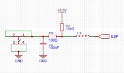
    How to protect ESP micro-switch inputs from ESD in a foil design? .

    What do you think of such input protection?

    I would be very grateful for your help.

    Regards M.
  • ADVERTISEMENT
  • Helpful post
    #2 21199638
    khoam
    Level 42  
    I would do it like this: a 3V3 transil close to the ESP pins, a series resistor (could be 100Ω, but could even be 1kΩ) and a 100 nF ceramic capacitor in parallel to the micro switch.

    MikolajMis wrote:
    to eliminate contact vibration to some extent
    .
    A software solution based on a hardware timer can be successfully applied.
  • #3 21199670
    MikolajMis
    Level 2  
    khoam wrote:
    I would do it like this: a 3V3 transil close to the ESP pins, a series resistor (could be 100Ω, but could be as low as 1kΩ) and a 100 nF ceramic capacitor in parallel to the microswitch.


    But I will leave the pull-up so that there is a steady state at the input?
    The use of a choke is not necessary/necessary/doesn't make sense/won't help/will spoil?

    I was considering a transil whereas I decided that I would only give it to the power line.

    Thanks for the reply!
  • Helpful post
    #4 21199675
    khoam
    Level 42  
    MikolajMis wrote:
    But I will leave the subsequence so that there is a steady state at the input?
    .
    Yes.

    MikolajMis wrote:
    The use of a choke is not necessary/necessary/doesn't make sense/won't help/will spoil it?
    .
    In this particular case I see no need for a choke. Unless it is for high frequency noise filtering ;) .
  • #5 21199684
    MikolajMis
    Level 2  
    khoam wrote:
    In this particular case I see no need for a choke. Unless it is for high frequency noise filtering
    .

    Actually a choke on the ESD makes no sense, and there will be no high frequency noise from the button.

    As for the transil put it as close as possible to the prock pin? For what reason? I was thinking closer to the input/button so that the pulse doesn't fly all over the board.

    Should I put the transil between the input line and ground or between 3.3V and the input line?

    Thanks a lot!
  • ADVERTISEMENT
  • Helpful post
    #7 21199776
    khoam
    Level 42  
    MikolajMis wrote:
    When it comes to the transil do you put it as close to the proctor pin as possible? For what reason?
    .
    It's supposed to protect the GPIO, so it should be close.

    MikolajMis wrote:
    Transil insert between input line and ground or between 3.3V and input line?
    .
    To ground.
  • #8 21200087
    MikolajMis
    Level 2  
    tos18 wrote:
    I have a solution.

    @tos18
    Seems like a good idea to me, as I use the same chip (USBLC6-2) for USB protection.
    @khoam, what do you think about using USBLC6-2 instead of single transils?

    On the other hand, I have another issue that came up today - I will probably have to separate the ESP PCB from the micro-switch PCB, I will connect them with a ribbon.
    For this reason I wanted to make sure that the previously discussed protections are sufficient to adequately protect the circuit? I will place the resistors, capacitors close to the buttons, while I will place the diodes on the PCB close to the ESP.

    Many thanks for your help!
  • #9 21200097
    tos18
    Level 42  
    I would place C12 on the other side of R36 (at R37)
    I would give all the filtering at the ESP
  • #10 21200101
    khoam
    Level 42  
    MikolajMis wrote:
    what do you think about using USBLC6-2 instead of single transils?
    .
    I am not in favour of "bundling" transils in a single cube. They are there to protect, so in the extreme case also to be destroyed, so that other circuits are not destroyed.
    Of course, you also have to consider the price of a single transil in both cases.
  • #11 21200116
    MikolajMis
    Level 2  
    tos18 wrote:
    I would put C12 on the other side of R36 (at R37)
    .
    And for what reason on the other side?

    khoam wrote:
    I am not in favour of "bundling" transils in one cube. They are there to protect, so in the extreme case also to be destroyed, so that other circuits are not destroyed.
    Of course, you also have to consider the price of a single transil in both cases.


    I understand, actually, but I'll probably suggest mainly on price and space, as I don't have much of it.

    I still have the outputs ( a few diodes on the case) there to protect something analogous to the inputs?
  • Helpful post
    #12 21200121
    tos18
    Level 42  
    MikolajMis wrote:
    And for what reason on the other hand?
    .
    Because together with R36, it will create a low-pass filter and dampen some contact vibrations.
  • #13 21200130
    khoam
    Level 42  
    MikolajMis wrote:
    I still have the outputs ( a few diodes on the housing) there to protect something analogous to the inputs?
    .
    I don't think this is necessary.
  • ADVERTISEMENT
  • #14 21200156
    MikolajMis
    Level 2  
    tos18 wrote:
    Because together with R36 it will create a low-pass filter and dampen some contact vibrations.
    .
    Indeed, thanks!

    khoam wrote:
    I don't think that's necessary.

    Thanks very much.
    In that case, we can end the topic.

    But finally I wanted to ask, referring to an older project with a 2x16 LCD display - because there I only protected the power supply with a transil and a capacitor, and did not protect the signal and data lines in any way - is transil protection enough here in case of some ESD?
  • #15 21201132
    khoam
    Level 42  
    MikolajMis wrote:
    Is the transil protection here sufficient in case of some ESD?
    .
    In this case it is the transils that protect against electrostatic discharge (ESD). They react very quickly (nanoseconds) and are able to withstand multiple surges without degradation.
  • ADVERTISEMENT
  • #16 21201173
    TvWidget
    Level 38  
    An ESD discharge will not occur unless the user touches conductive parts or the insulator is punctured. If you have a plastic enclosure then possible ESP damage is very unlikely. However, if you want to apply some protection then a series resistor should suffice. Elements such as transils or varistors are used when energy absorption of the discharge is required. The energy is assessed and the parameters of the element are adjusted accordingly.
  • #17 21201420
    MikolajMis
    Level 2  
    khoam wrote:
    In this case, it is the transils that protect against electrostatic discharge (ESD). They respond very quickly (nanoseconds) and can withstand multiple surges without degradation.


    TvWidget wrote:
    If you want to apply some protection, however, a series resistor should suffice. Elements such as transils or varistors are used when energy absorption of the discharge is required. The energy is assessed and the parameters of the element are adjusted to suit.


    So I will still use transils for ESD protection and in series resistors for protection, and what resistor values? 100R will be suitable? Apply the above protections to all lines - RS, R/W, E, DB0-DB7(I only use 4 data lines)?
  • Helpful post
    #18 21201489
    TvWidget
    Level 38  
    ESD discharges have very fast rise times. In other words, principles similar to those for high frequencies apply when designing protection. The layout of the paths, the correct component arrangement and the size of the components used are therefore very important.
    The higher the value of the series resistor, the more effective the ESD protection. Instead of pull-up resistors, the input can be polarised by software in the ESP. In this case, the value of the series resistor can be, for example, 1k or even more. The probability of enough energy getting through it to damage the ESP is negligible even if there are no additional components behind the resistor.
  • #19 21201531
    MikolajMis
    Level 2  
    TvWidget wrote:
    Instead of pull-up resistors, the input can be polarised by software in the ESP. In this case, the value of the series resistor can be, for example, 1k or even more. The probability of enough energy getting through it to damage the ESP is negligible even if there are no additional components behind the resistor.

    However, I would prefer the subsequences to remain. But for a 1k resistor in series this will come out a voltage divider and there will be 0.3V on the ESP pin when the button is pressed. Do you think it can stay like that or reduce the resistor though?

    Thanks a lot for your help!
  • Helpful post
    #20 21201591
    TvWidget
    Level 38  
    You can give the polarising resistor before the series resistor.
    However, there is no single ideal solution. Each has some advantages and disadvantages. You design the device. You know what environment it has to work in and what kind of interference it may be exposed to, and so on. So you have to make the decision yourself.
    Getting back to the substance of the matter, in my opinion you should consider the probability of your finger touching the input line. Applying protection just for the sake of being able to apply it makes no sense.
  • #21 21201679
    khoam
    Level 42  
    MikolajMis wrote:
    However, I would prefer the pull-ups to stay.

    The internal pull-up resistors on the ESP32 are typically around 40 kΩ to 50 kΩ, which is a lot, or lower noise immunity. If the circuit does not require any special power consumption restrictions, it is therefore better to use external pull-up resistors with lower resistance.
  • #22 21204717
    MikolajMis
    Level 2  
    TvWidget wrote:
    Returning to the substance of the matter, it is my opinion that you should consider the likelihood of your finger touching the input line. Applying safeguards just for the sake of being able to apply them makes no sense.


    The PCBs are bolted to the metal front via steel spacers, so ESD can somehow transfer to the PCB surface, that's my understanding and that's why I want to protect against it.

Topic summary

The discussion focuses on protecting ESP micro-switch inputs from electrostatic discharge (ESD) in a foil design within a plastic enclosure. The proposed input protection includes a pull-up resistor to supply voltage, a capacitor to ground parallel to the button, a 100Ω series resistor to reduce contact bounce, and a choke, though the choke is generally considered unnecessary for ESD or button noise filtering. Recommended ESD protection involves placing a Transil diode close to the ESP GPIO pin, connected between the input line and ground, to clamp voltage spikes effectively. Alternatives such as the USBLC6-2 chip, commonly used for USB protection, were suggested for robust ESD and EMI filtering. Series resistor values can range from 100Ω to 1kΩ or higher, balancing protection and signal voltage levels; higher resistor values improve ESD protection but may cause voltage drops. External pull-up resistors with lower resistance than the ESP internal pull-ups (40-50 kΩ) are advised for better noise immunity. The layout and component placement are critical for effective ESD protection, especially when the PCB is mounted near metal parts that can conduct ESD. Protection on output lines can be analogous, using diodes or similar components. Overall, a combination of series resistors, capacitors, and Transil diodes near the ESP pins is recommended for professional ESD protection in such designs.
Summary generated by the language model.
ADVERTISEMENT