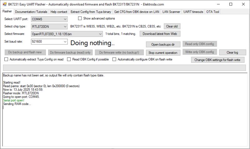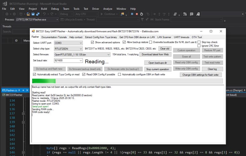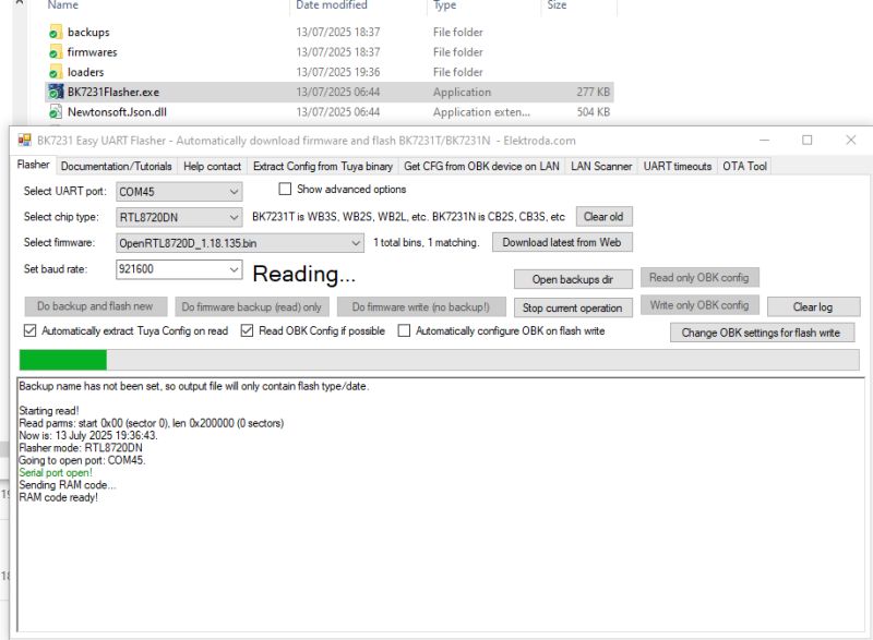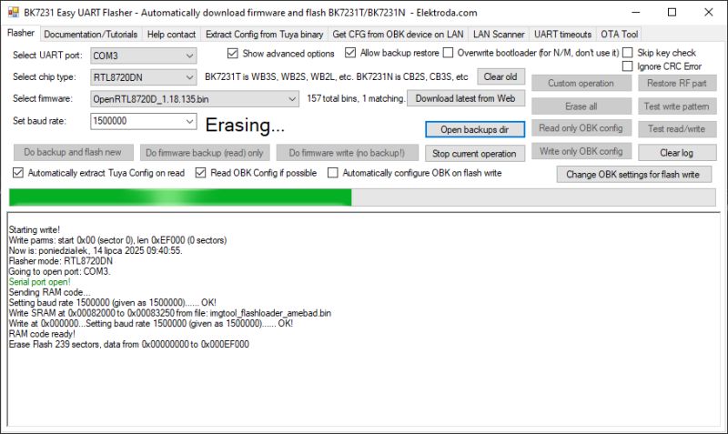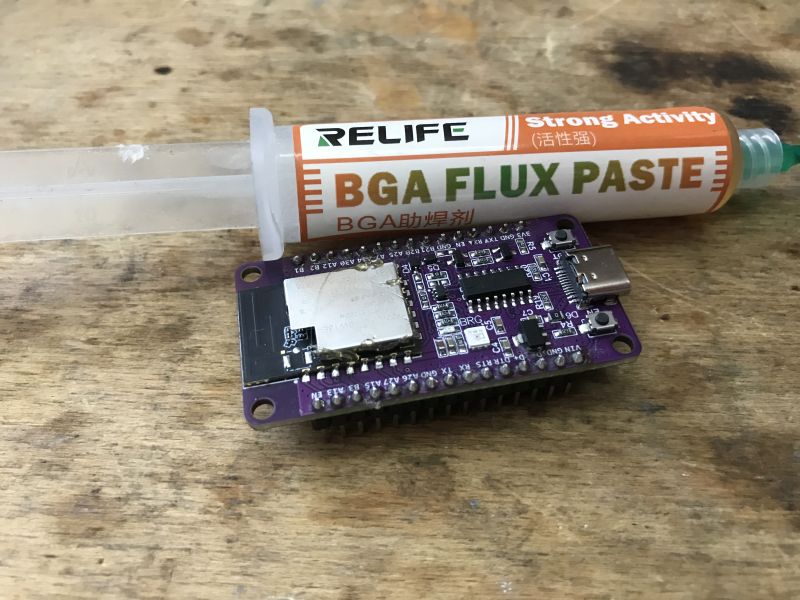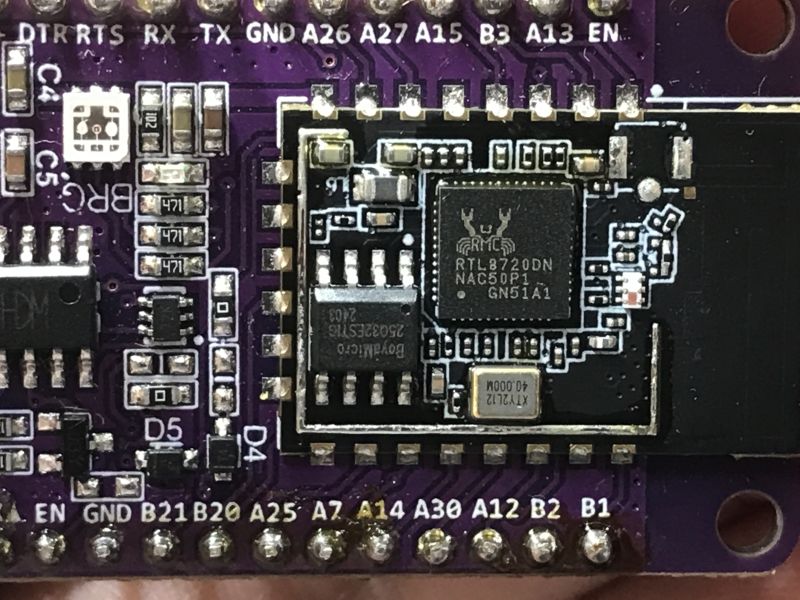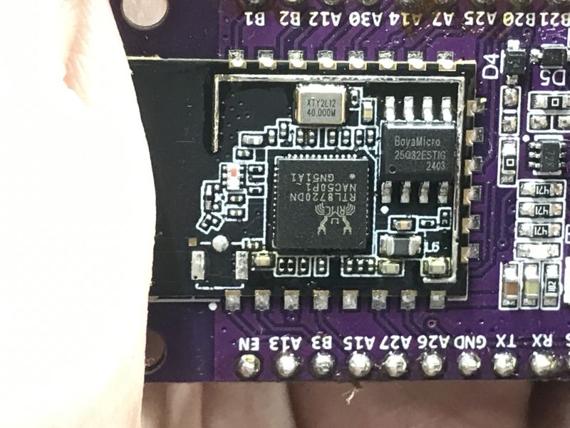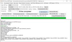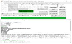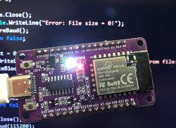
I've been recently experimenting with simple flashing code for BW16E (RTL8720DN AmebaD) board, in theory also working for any of RTL872xDx family. RTL8720DN is a WiFi (2.4GHz and 5GHz) and Bluetooth (LE 5.0) module that features dual core CPU using KM4 and KM0 cores. It can be bought for as low as 1$. Here I will show my experiences with programming this board and briefly describe the flashing process.
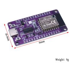
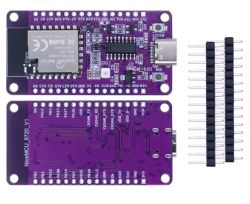
The goal of this topic will be to create a simple C# flash tool that can write OpenBeken firwmare port to RTL8720DN.
First experiments
I've started by looking for simple and easy to use flashers supporting RTL8720DN. After some time, I've decided to RTL872xDx python tool.rar that was shown previously on our forum. Reading seemed to work well, however we had to add longer delay to function waiting for MCU response. Read command:
python rtltool.py -p COM7 -b1500000 rf 0x0 0x400000 bw16_rtltool.bin
I couldn't get it to write, though. It worked for other boards, but failed on RTL8720DN every time:
python rtltool.py -p COM4 -b 100000 wf 0 ff1_4mb.binError message was:
error: Set Flash StatusSame problem was reported by other users. I played around with the code and figured out that the culprit is the unsupported flash unprotect, which seems to work on other RTLs, but breaks on RTL8720. Commenting it out solved the issue and flashing proceeded correctly.
Simple flasher implementation
My simple flasher is available on Github, here:
https://github.com/openshwprojects/SharpRTL872xTool
Released repository also contains sample scripts and dumps:
https://github.com/openshwprojects/SharpRTL872xTool/tree/main/samples
If there is no imgtool_flashloader_amebad.bin next to downloaded exe, make sure to download it from there!
The flash read procedure seems fairly simple. It can be divided into the following steps:
- first, MCU is put in flashing mode and reset via RTS/DTS pins
- next, a simple xmodem loader code is read from file and put into the device RAM (this step is skipped if code section header bytes are already present in RAM)
- finally, flash is read in 1024/128 chunks via Xmodem protocol
Similar approach is used for flash write, altough then, first required sectors are erased and then written.
Let's consider procedure in details.
Initial reset sequence
BW16E board, like many other boards, features RESET and BOOT pins. They are controlled via CH340 DTR and RTS lines. Boot must be held low while RESET is released in order to enter flashing mode.
Code: C#
Command system
Command system is very simple. First N bytes are written and then flasher waits for a single expected byte. If no expected response is met, then communication is assumed to have failed. I am suprised by the simplicity of this approach, I was rather expecting at least some kind of CRC check somewhere in the way, but original rtltool is missing it as well.
Code: C#
Baud setting
Baud setting is tricky, because the MCU would just lose the communication if not notified about change. That's why there is a specific packet that first sends new value to the MCU, then waits for acknowledge, and then, finally, adjusts the baud.
Code: C#
Writing RAM code
To communicate with flash memory, a helper binary (imgtool_flashloader_amebad.bin) must be uploaded into MCU SRAM. This file contains the flashloader used by Realtek’s official tools. Before uploading, the flasher checks whether the RAM already contains a valid loader by examining the first 4 bytes. If not present, the file is sent using XMODEM protocol.
Code: C#
NOTE: 33 dec is 0x21 hex, and so on.

Writing memory
After RAM is loaded with the loader code, commands like erase, write, and read can be executed. Writing uses XMODEM and automatically breaks data into 1024 or 128 byte chunks, depending on how much remains.
Code: C#
Test scripts
To verify and experiment with the flasher tool, I prepared several simple batch scripts that perform common operations such as erasing, writing, and reading flash memory. These scripts automate the command line usage of the flasher executable and help to easily reproduce basic flash operations.
The first script, erase_4mb.cmd, erases the first 4 megabytes of flash starting at address 0. This is useful for clearing the entire main flash region before writing new firmware or data. OpenBeken was not booting correctly without it! The erase command (ef) takes the start address and length as parameters:
RTL872xDx_Flasher.exe -p COM3 -b 1500000 ef 0 0x400000
pause
Next, write_obk.cmd writes a full firmware image file to the flash memory starting at address 0. This script is essential for flashing a new program image to the device after erasing:
RTL872xDx_Flasher.exe -p COM3 -b 1500000 wf 0 OpenRTL8720D_1.18.135.bin
pause
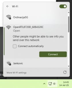
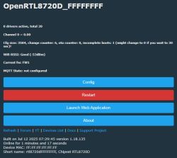
OpenBeken then should be able to boot:

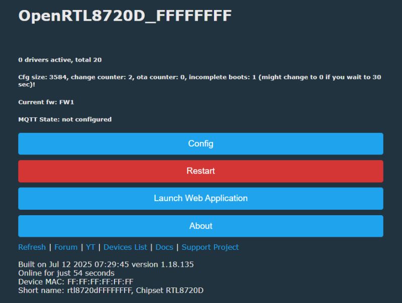
However, I've added some more test scripts. They operate on smaller flash section, so are quicker to run.
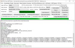
For a simple test, try erase_4096.cmd and then read_4096_dump_bin.cmd, you should get:
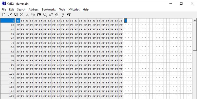
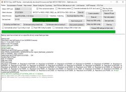
After doing write_lorem_ipsum.cmd the read_4096_dump_bin.cmd should give:
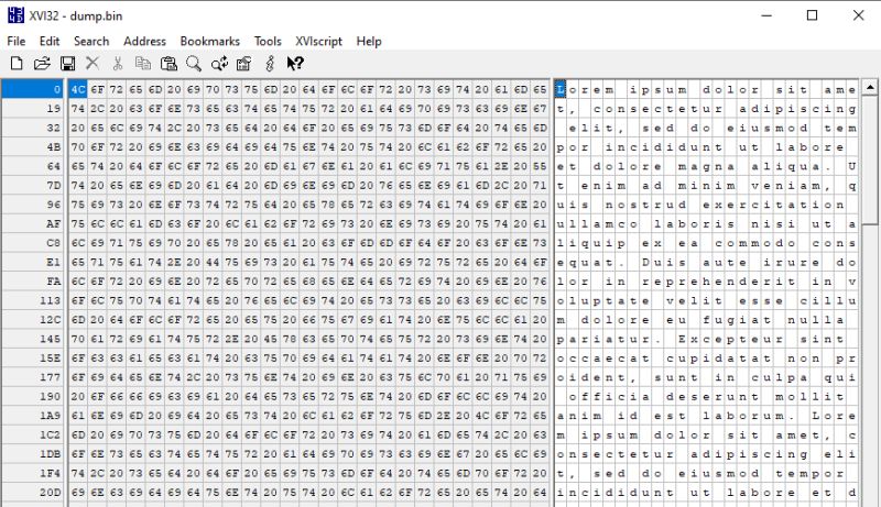
Similary, read back after write_obk.cmd should show:
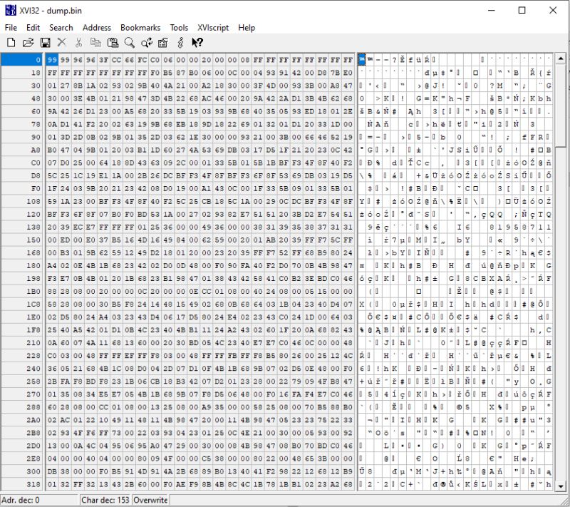
This way you can reliably check whether read and write works.
Summary
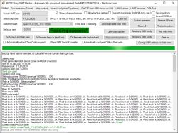
The mentioned repository should provide a basic method for flashing RTL8720DN. I am not sure if it will work for other RTLs from the same family, as I omited the flash protection code. Soon I'm going to try them as well, but first I will most likely integrate ported code with our easy flasher
Do you have any similar RTL boards? Let us know if this flashing solution works for you!
Cool? Ranking DIY Helpful post? Buy me a coffee.


