logo elektroda
logo elektroda
X
logo elektroda

Good MOSFETs at 5V for free? Recovering parts from an old PC motherboard

p.kaczmarek2 4368 20
ADVERTISEMENT
Treść została przetłumaczona polish » english Zobacz oryginalną wersję tematu
  • Old computer motherboard with attached CPU cooling fan. .
    What can a hobbyst recover from an old computer motherboard? Where to get good MOSFETs to drive from 5V, from an Arduino, preferably ones for higher currents, with low resistance in the open state? They can be just recovered from such a motherboard - here I will show how and briefly test such a transistor in practice.
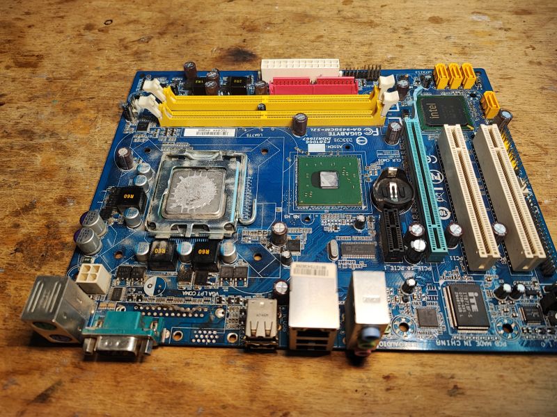
    The adventure begins when an old PC falls into our hands, which is probably not a rare situation. At my place, every now and then someone throws such equipment away. Here I have the motherboard from already dismantled PC:
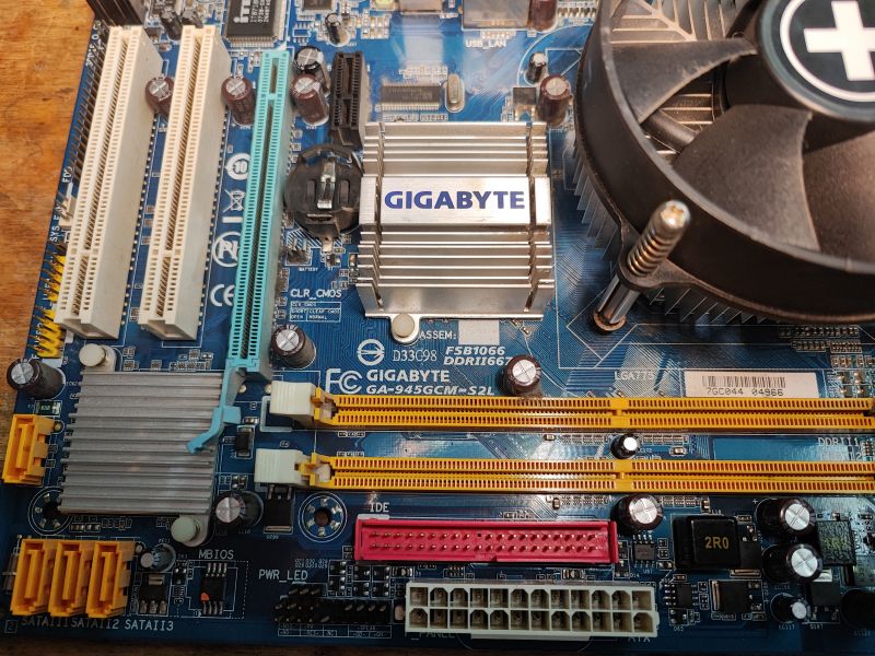
    Close-up of a GA-945GCM-S2L motherboard by Gigabyte with a mounted fan and heatsinks. .
    GA-945GCM-S2L, additionally dead (even after CMOS battery replacement and reset). If it worked, you could still try to give it to someone further for a token amount or assemble a retro kit on it, but I will scrap this one, since it's dead.
    I first removed the heatsinks:
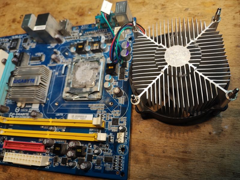
    Photo of an old GA-945GCM-S2L motherboard with a mounted heatsink. Old computer motherboard with visible components and slots. .
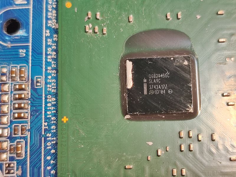
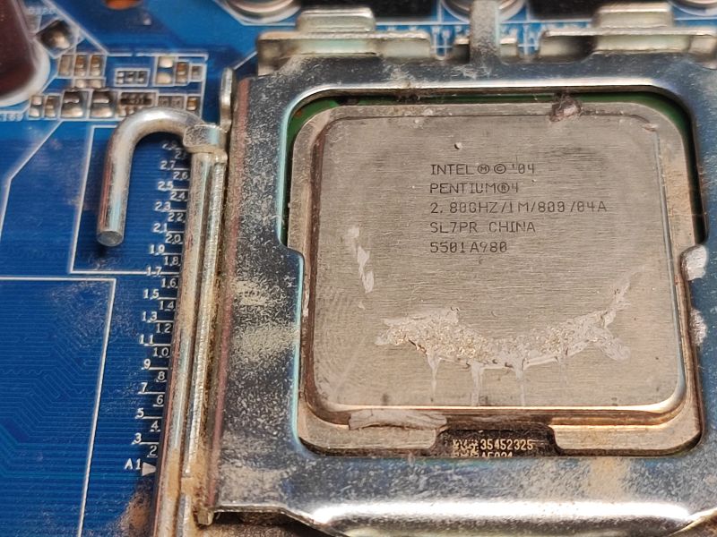
    I took pictures of what sits on this board:
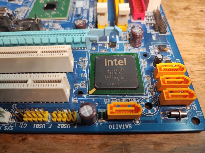
    Close-up of an old Intel motherboard with visible connectors and components. Image of GA-945GCM-S2L motherboard with QG82945GC chip. Close-up of an Intel Pentium 4 processor on an old motherboard.
    - Intel Pentium 4 2.80GHz
    - QG82945GC SLA9C
    - INTEL NH82801GB
    By the way, interesting to note how my camera caught the focus on the reflection when taking one of the photos:
    Spoiler:
    Close-up of a motherboard surface with a camera lens reflection.
    .
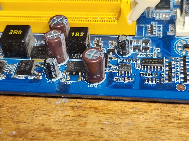
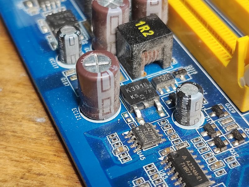
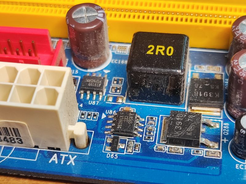
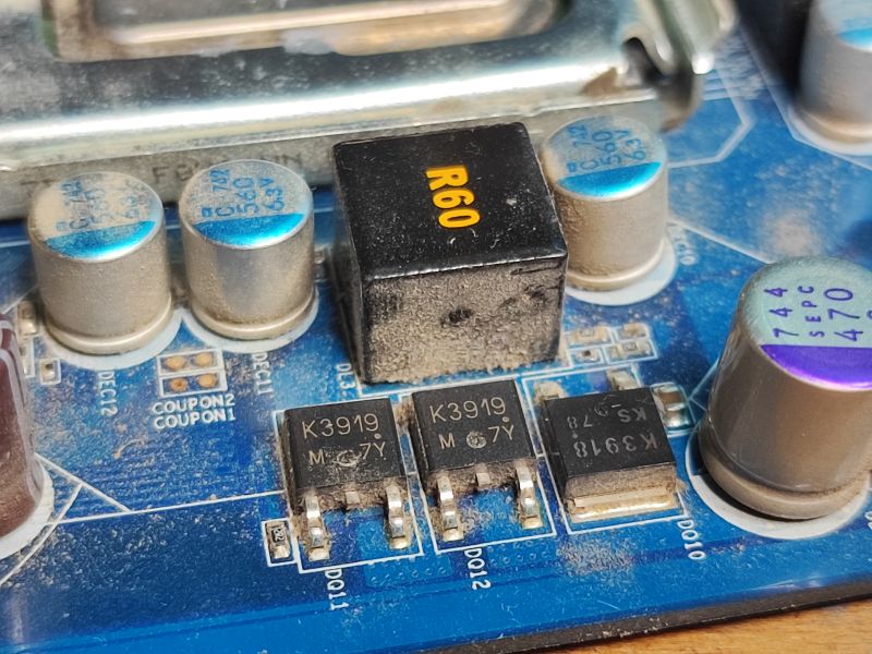
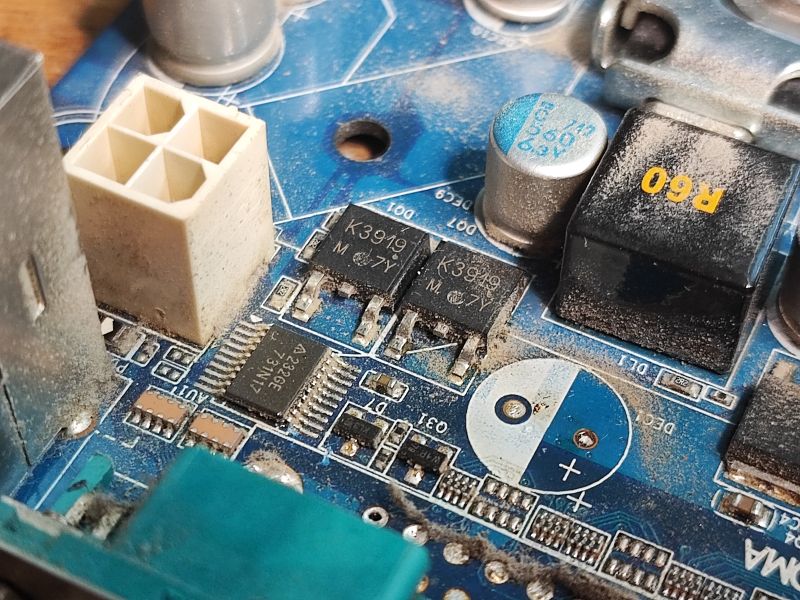
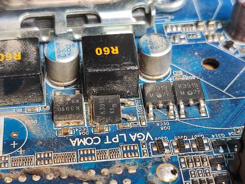
    So on the board we have a bit of inverters and surface mounted transistors:
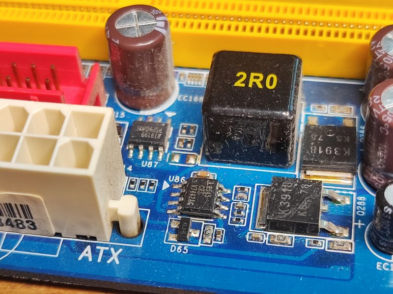
    Part of a damaged motherboard with visible electronic components. Close-up of electronic components on a computer motherboard Close-up of electronic components on a motherboard, including K3918 transistors and capacitors. Close-up of a motherboard with visible MOSFET transistors and other elements. Close-up of electronic components on a motherboard, including K3919 and K3918 transistors. Close-up of an old motherboard with electronic components K3919 and others. Close-up of an old motherboard with electronic components K3919 and others.
    Close-up of components on a computer motherboard, including K3919 and K3918 transistors. .
    These are primarily used in step-down inverter circuits, for example I see one based on the MAX8545 in the picture. They generate lower voltages for the CPU, memory, etc:
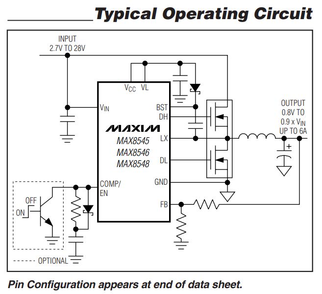
    Typical operating circuit of the MAX8545 converter .
    The topic is about transistors, but it's hard not to mention the Flash memory with SPI interface - only 8 legs, also to be soldered and used:
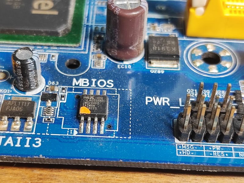
    Close-up photo of a section of the GA-945GCM-S2L motherboard showing various electronic components. .
    It contains BIOS.
    The question of desoldering out remains.
    It is best to use hot air, although you can also use a heat gun as long as you do not care about the board. Then you will practically certainly damage it and it has to be done outside. The fumes are toxic. In addition, there is a high risk of exploding our capacitors, you can remove them separately beforehand. As for the hot air itself, I refer you to the topic/series:
    Hot air station 858 for £150 - what cheap hot air to fly off the boards of a laptop, computer? .
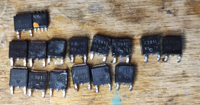
    This is how I recovered the components:
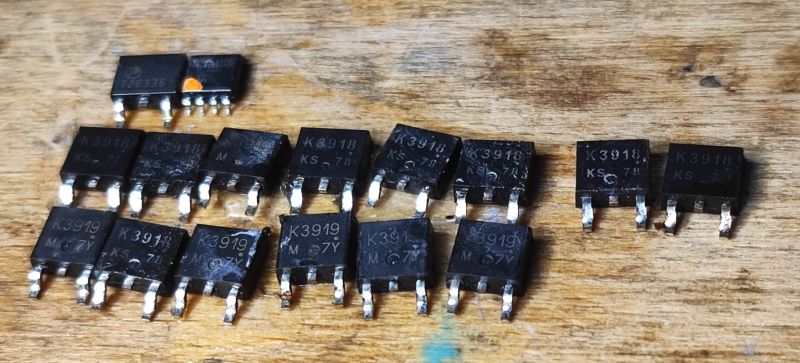
    A set of desoldered MOSFET transistors from a motherboard on a wooden table. Desoldered MOSFET transistors from a motherboard. .
    The soldered transistors are practically only K3919 and K3918. More precisely:
    - 2SK3919 - 20V 64A 36W 5.6mΩ
    - 2SK3918 - 20V 48A 29W 7.5mΩ
    Let's therefore open the catalogue note of 2SK3919:
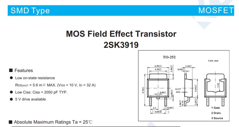
    Technical documentation of the 2SK3919 transistor, detailing its specifications and TO-252 package diagram. .
    Already on the first page we have important information for us:
    - resistance in the open state (RDS(on)) and drain current
    - information about the possibility of driving it from 5V (e.g. from Arduino)
    - leads, so that we do not have to test/check with a multimeter
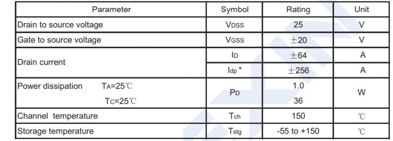
    MOSFET transistor parameter table. .
    Only that the information on the first page is given for specific conditions (see e.g. Vgs in brackets) and if you really want to know what parameters to expect e.g. when controlling a gate with 5V, you need to look at the On to the charts, or at least to the table:
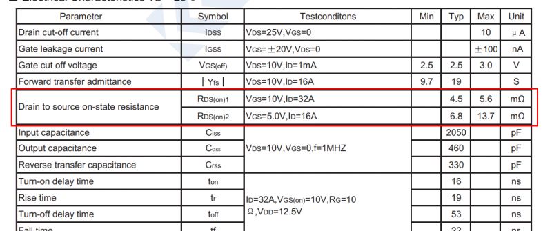
    Diagram showing transistor electrical characteristics with highlighted on-state resistance. .
    Here you can see that at Vgs=10V the RDS(on) will be slightly lower than at 5V, but does it matter that much to us in amateur conditions.... we are not designing a new product here, we just want to post something for free.
    However, a table is not enough - let's have a look at the graph, for example RDS(on) as a function of drain current - here we have separate curves for Vgs=5V and 10V:
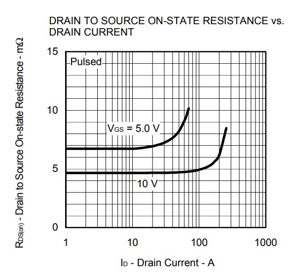
    Graph of MOSFET on-state resistance versus drain current .
    You can also see a graph of the drain current as a function of Vgs if, for example, you want to experiment with even smaller Vgs:
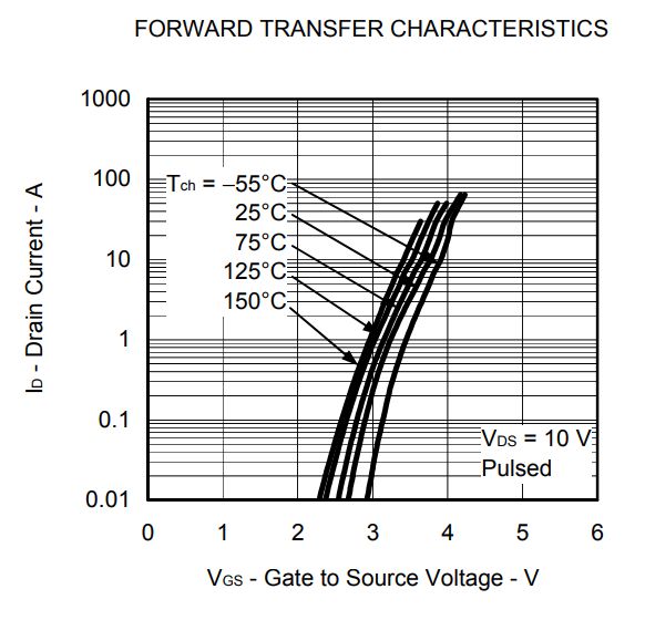
    Transfer characteristic graph of a transistor showing current attenuation markings. .
    But I don't want to get into the theory here, so armed with the knowledge that 5V is enough for us, we run a simple Arduino sketch for demonstration purposes and connect the MOSFET. As a test, we will make a simple dimmer based on changing the PWM fill:
    Code: C / C++
    Log in, to see the code
    .
    The sketch above loops the PWM fill from 0 to 100% and from 100% to 0. We upload it to the Arduino.
    Of course a simple dimmer is better done at least on an NE555 and you don't need a microcontroller for that, but I had an Arduino at hand and this is just a demonstration.... additionally with NE555 you could use a higher voltage and here I wanted to test the operation specifically at 5V.
    I soldered the MOSFET to a piece of copper-coated laminate to give a bit better heat dissipation. Other than that, standard as in many schematics:
    - source to ground
    - gate via resistor to PWM (you can also give a resistor to ground - pull down)
    - drain to LED strip, which is connected to the power supply
    It worked out like this for me:
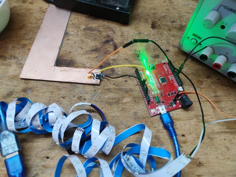
    Experiment with Arduino and MOSFET on a workshop table .
    Testing. The dimming is working:


    .
    But that's rapt at currents up to 30mA, so it doesn't mean much.... we are interested in higher currents.

    That's why I then ran a slightly higher current through the MOSFET as a test. First by controlling it from the Arduino and then simply from 5V. I settled on 3A at 13V. I used ordinary high-power resistors on a heatsink as the load. My wires were warmer than the transistor itself, and I waited a while.... The resistors from the load were heating up the hardest. And the MOSFET continues to work.
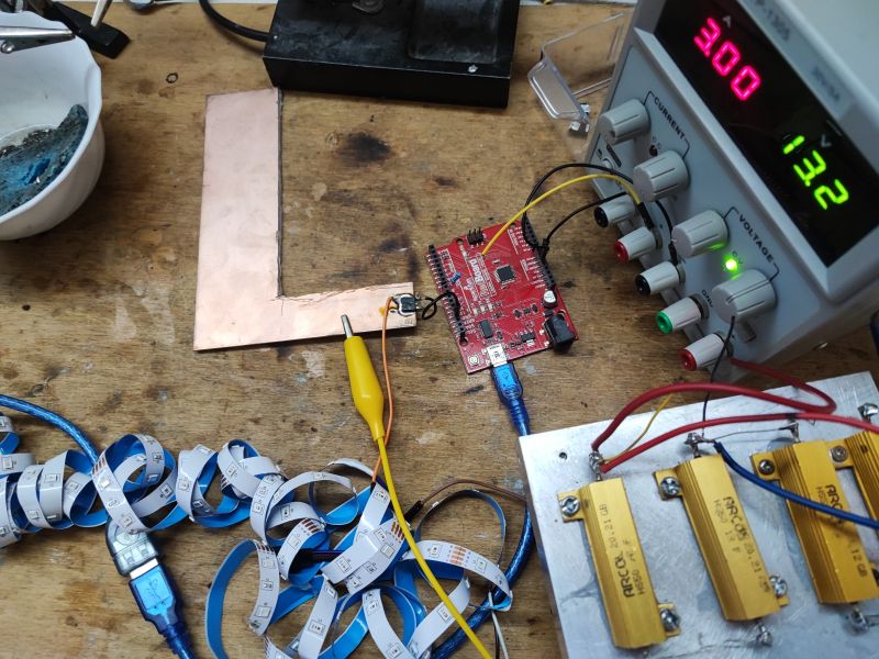
    Arduino connected to a MOSFET and LED strip on a test setup .

    To sum up, in my opinion, it is worthwhile for a beginner to recover some components from the motherboard and they are not just a "workshop decoration" or "equivalent of a stamp collection for an electronics engineer", but really can be used in DIY and driven at least with Arduino. In addition, in my case these MOSFETs were essentially only two types, and this is also a plus, because having several of each of the same type you can make more. As for the operation of the MOSFET itself, I haven't gone into that here, and I would refer you to a good book if you have any questions, as the basic parameters are really worth knowing and understanding.
    Now the question is, what else can be made from these transistors? Maybe some dimmer, but this time without the MCU? Or maybe desolder and reuse whole step down converter? Or maybe make a dummy load? What ideas do you have? .

    Cool? Ranking DIY
    Helpful post? Buy me a coffee.
    Do you have a problem with Arduino? Ask question. Visit our forum Arduino.
    About Author
    p.kaczmarek2
    Moderator Smart Home
    Offline 
    p.kaczmarek2 wrote 11825 posts with rating 9927, helped 564 times. Been with us since 2014 year.
  • ADVERTISEMENT
  • #2 21247372
    VPSA132
    Level 25  
    I see the use of these transistors mainly in LED drivers e.g. to amplify weak drivers.
    Sacrifice one piece and see if it will last at PWM 50% at 24V and 1.5A current? How fast will it get through it and if at all :D . Maybe it can do it.
  • ADVERTISEMENT
  • #3 21248537
    acctr
    Level 38  
    If you don't feel sorry for the board, you can cut it into smaller pieces, in which case soldering the components is easier as there is less mass to be heated. Preferably with a saw blade to avoid stress.

    I also recover transistors from such boards. I used them, for example, in a synchronous rectifier on some Linear IC, a rectifier for a classic 12 V/8 A power supply.

    p.kaczmarek2 wrote:
    A maybe an artificial load?
    .
    Contrary to the perception created by the large current in the catalogue, SOA counts in artificial load.
    Helpful post? Buy me a coffee.
  • #4 21249020
    sq3evp
    Level 37  
    What do you use for soldering? Hot airs or a standard soldering iron?
    I once soldered a socket without damaging the plastic, but it was obvious that the board needed heat to release the solder.
  • #5 21249325
    japycz321
    Level 26  
    Whatever.... The key is to heat the whole board in advance. The quickest way to achieve this effect is to use a heat gun from a distance, not too close. Then, for the tin to release, it is enough to raise the temperature by a much smaller amount, e.g. 100 degrees, and not 200 as with a completely cold plate. It is also worth having a good flux and adding lead tin.
  • #6 21249587
    dudik56
    Level 17  
    p.kaczmarek2 wrote:
    Now the question is, what else can be made of these transistors? Maybe some dimmer, but this time according to the art, i.e. without the MCU? Or maybe solder and run the whole inverter? Or maybe an artificial load? What ideas do you have?
    .
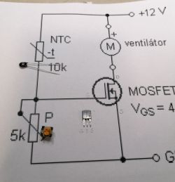
    I often use such transistors for simple "automation" cooling of inverters, power supplies and the hot side of camping absorption refrigerators. ;) .
    This works reliably.

    Electrical diagram with electronic components like MOSFET transistor and NTC thermistor. .
  • #7 21250806
    zgierzman
    Level 31  
    p.kaczmarek2 wrote:
    demonstrate a simple Arduino sketch
    .

    This is some kind of linguistic absurdity.
    The English word "sketch" is Polish for "sketch." - which corresponds perfectly to the idea of such a skeletal, prototype programme.

    On the other hand, a 'sketch' in Polish is an artistic performance intended to provoke laughter.

    Why, then, use such meaningless calques from English, when in Polish there is a perfect term for it, which is also a dictionary translation?

    I don't use Arduino, but if "sketch" is in the Polish version of the menu, shame on the translator.
    And if it's "sketch", it's hardly worth transcribing phonetically, as it creates meaningless statements.
  • ADVERTISEMENT
  • #8 21252029
    piotrkol7
    Level 39  
    acctr wrote:
    When the board doesn't feel sorry for you you can cut it into smaller pieces, then soldering the parts is easier because there is less mass requiring heating. Preferably with a saw blade to avoid stress.

    Sheet metal shears also work well ;) .

    sq3evp wrote:
    I once managed to solder a socket without damaging the plastic

    japycz321 wrote:
    Whatever.... The key is to preheat the whole board.
    .
    Question what socket, but in general whether sockets or threaded sockets, the key is strong heating from the bottom of the board. Although PCIe sockets are quite hard to solder out of such a board entirely, rather there is always some pin left.

    Added after 1 [minute]: .

    I have been recovering power sockets from motherboards/graphics cards. They are cool to use in a workshop setting, you can use them to power your own designs from a computer power supply for example.
    Helpful post? Buy me a coffee.
  • #10 21252078
    piotrkol7
    Level 39  
    Apparently so, but it's quicker than using a saw blade and you don't inhale the dust created when cutting the insert.
    And if the insert is only for part recovery, why bother with stress?
    Helpful post? Buy me a coffee.
  • #11 21252498
    acctr
    Level 38  
    piotrkol7 wrote:
    Yes, but faster than with a saw blade and you don't inhale the dust created when cutting the tile.
    .
    It is not faster because you can only cut in a straight line. To cut a square from the centre you need to make at least 2 long cuts. With a hair saw you can cut any shape inside the tile.
    You can always cut wet and in a mask (health and safety).

    piotrkol7 wrote:
    As you tile only for recovery of parts, why bother with stresses?
    .
    Because you're cutting into pieces for something and the reason is certain components can fail under stress.
    Helpful post? Buy me a coffee.
  • #12 21258823
    chemik_16
    Level 26  
    from what I have seen how they disassemble it in china they put the board on the heater/heated tin and after 10sec they hit the board on the ground and all the parts fall off :D

    But that's how they tend to dismantle only the expensive parts, like branded frames or chipsets, i.e. what they can't produce themselves/is expensive, the rest goes into the rubbish.

    Recently I also dismantled these mosfets for the pwm controllers on the esp, I used a heat gun, but I don't recommend it. While everything comes off nicely you have to be careful with the capacitors as they shoot up like fireworks.
  • #13 21261967
    bobeer
    Level 28  
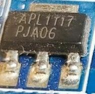
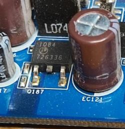
    Did you know that Jfet power transistors used in diy 'audiophile' amplifier designs can be found in old motherboards ? ;) .
    A long time ago I pulled 3 pieces out of some board and was very surprised that they had a short circuit without applying a voltage to the gate ;)
  • ADVERTISEMENT
  • #15 21262239
    bobeer
    Level 28  
    acctr wrote:
    It's interesting, do you remember what board this is and what the transistors and driver are?
    .
    It was around 2004, some megabyte or something like that, definitely not asus or abit. More likely under amd. The pcb colour may have been blue. This much I remember :) .
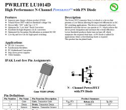
    Technical documentation page for the PWRLITE LU1014D transistor. .
  • #16 21263675
    piotrkol7
    Level 39  
    bobeer wrote:
    Did you know that Jfet power transistors used in diy 'audiophile' amplifier designs can be found in old motherboards ? ;) .
    A long time ago I pulled 3 pieces out of some board and was very surprised that they had a short circuit without applying voltage to the gate ;)
    .
    And that's right. I've been able to find it in newer boards too.
    Helpful post? Buy me a coffee.
  • #17 21267385
    drunek
    Level 25  
    What are these JFETs responsible for there?
  • #18 21270248
    żarówka rtęciowa
    Level 37  
    Hello

    To facilitate the removal of components from such a board, it could be heated with an infrared heater of sufficient power.
  • #19 21271091
    sq3evp
    Level 37  
    drunek wrote:
    What are these JFETs responsible for there?
    .
    Maybe as switches they work with such a low transition resistance?
  • #20 21272154
    bobeer
    Level 28  
    sq3evp wrote:
    Maybe as switches they work with such a low transition resistance?
    .
    More like ordinary inductance keying in the inverter.
  • #21 21272508
    sq3evp
    Level 37  
    I don't know, maybe so. As a switch it will also be suitable - with such a low resistance very little connector loss.

Topic summary

The discussion revolves around recovering MOSFETs from old PC motherboards, specifically for use with 5V systems like Arduino. Participants share techniques for disassembling motherboards, emphasizing the importance of proper heating methods to avoid damaging components. Suggestions include using heat guns, infrared heaters, and cutting tools to facilitate the removal of transistors. Users mention the application of these transistors in LED drivers, synchronous rectifiers, and automation cooling systems. There is also a mention of JFET power transistors found in older boards, with discussions on their functionality and suitability for low-resistance switching applications.
Summary generated by the language model.
ADVERTISEMENT