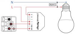
In 'non-neutral' schemes, the current always flows either through the load, usually a light bulb, or additionally through a parallel shunt. The current intensity is so small in the "zero" state that the bulb does not light up.
Without advertising this particular manufacturer, here an example diagram for the Shelly Dimmer 2:

.
In this case, it is a dimmer-equipped device, structurally adapted for such operation. The requirement for correct operation, however, is bulbs that will respond correctly to low current, such as dimmable LEDs. If this is not the case, the whole thing may not work properly, which most often manifests itself as blinking light.
 .
.