logo elektroda
logo elektroda
X
logo elektroda

Make any smart relay no-neutral?. Explanation

spin55 4347 14
ADVERTISEMENT
  • This assembly is universal. Suitable for all types of AC devices.
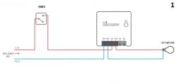
    Make any smart relay no-neutral?. Explanation

    You can control the device manually through SW1 but remotely only when SW1 Closed.
    And you need to configure Startup like this:

    Make any smart relay no-neutral?. Explanation

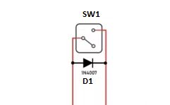
    When SW1 opened, Sonoff Offline. In order for Sonoff to stay in line with SW1 Open, we added D1.
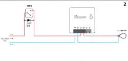
    Make any smart relay no-neutral?. Explanation

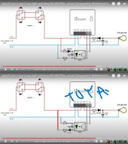
    Now with SW1 closed the bulb turns on normally, but when SW1 is open the bulb flashes. To correct that we add this:
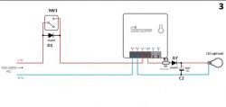
    Make any smart relay no-neutral?. Explanation

    R3 limits the current through D7 when C2 is discharged when the device is connected to the AC mains. C2 charges through D7 during the AC positive half cycle and begins to discharge through the bulb during the 10 millisecond AC negative half cycle. The bulb is running on DC despite being an AC device (explained later).

    We already eliminated the flicker but when opening or closing SW1 the bulb stays on. We need a trigger:
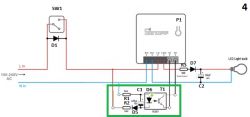
    Make any smart relay no-neutral?. Explanation

    But for it to work we need to configure this:

    Make any smart relay no-neutral?. Explanation

    Now we can turn the bulb on and off by controlling Sonoff via S1-S2. When SW1 closed, T1 conducts and closes S1-S2. When SW1 open, T1 does not conduct and opens S1-S2.

    Why are Sonoff and bulb working if they are AC devices?

    Because they work internally at DC. That's why we can't connect a device that works internally with AC like a ceiling fan, for example. But there are DC fans, I think these could work with this assembly for the same reason that Sonoff and led bulb do.

    AC devices work with assembly 1, which is universal, as long as the current consumed is less than what Sonoff's internal relay can withstand (usually 10 or 16A).

    https://www.elektroda.com/rtvforum/topic3969629-30.html#20536819

    Cool? Ranking DIY
    About Author
    spin55
    Level 17  
    Offline 
    spin55 wrote 209 posts with rating 39, helped 16 times. Been with us since 2022 year.
  • ADVERTISEMENT
  • ADVERTISEMENT
  • #3 20545054
    spin55
    Level 17  
    Thanks for the link. I did not know that.
  • #4 20546305
    ferbulous
    Level 18  
    @kaczmarj
    I’ve bought it before as well, what’s great is you can flash tasmota/esphome since ewelink diy mode works and it’s small enough to fit behind the switch.

    Not ideal for 2 way switches unless you already have those extra cables in your existing 2 way wiring though. That’s where this no neutral hack comes in for the tuya module.

    Added after 8 [hours] 46 [minutes]:

    @spin55
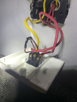
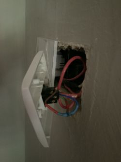
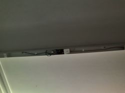
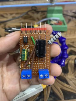
    Finally got it installed on my 2 way light switch for the bathroom and it’s working nicely


    Make any smart relay no-neutral?. Explanation Make any smart relay no-neutral?. Explanation Make any smart relay no-neutral?. Explanation Make any smart relay no-neutral?. Explanation
    Make any smart relay no-neutral?. Explanation
  • #5 20546767
    spin55
    Level 17  
    We already knew it worked.
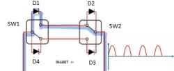
    If it works with one wall switch, it works with two or three.
    Enjoy it!!
    This:
    Make any smart relay no-neutral?. Explanation
    And this is the same:
    Make any smart relay no-neutral?. Explanation
  • ADVERTISEMENT
  • #6 20546786
    ferbulous
    Level 18  
    @spin55 my wife just called and complained the ac’s 20a switch is not turning on and asked me to check on it.
    Oddly enough this happened after i did the modification for the 2 way switches and both (light switch & ac) are on different breakers.
    Could this be somehow related? Just asking since it’s gonna be a while till i get back home
  • #7 20547051
    spin55
    Level 17  
    I think the same as you, that they are different circuits, but you never know.
    There is only one way to clear up doubts: disconnect the assembly and see what happens.
  • #8 20549505
    ferbulous
    Level 18  
    @spin55 looks like it’s not related
    Gonna need to call someone to check it since replacing 20a switch doesn’t fix it

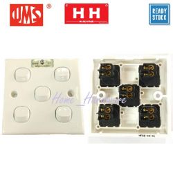
    By the way i have a 5 Gang switch, could i just use 1 diode and loop from live to other gangs or just use 5 diodes
    Make any smart relay no-neutral?. Explanation
  • ADVERTISEMENT
  • #9 20549650
    spin55
    Level 17  
    ferbulous wrote:
    By the way i have a 5 Gang switch, could i just use 1 diode and loop from live to other gangs or just use 5 diodes


    I don't understand what you want to do. If you do a freehand sketch I could try to give you a coherent answer.
  • #10 20633599
    dead2112
    Level 5  
    Hello, is there any difference between using a single capacitor? Also, does the capacitance matter? Some have a 0.4 uF and anothers user 2 uF or 4.4 uF.
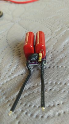
    I have seen some devices that includes only a single capacitor but others come as a built in module incluiding a resistor and a thermistor like this:
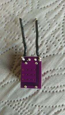
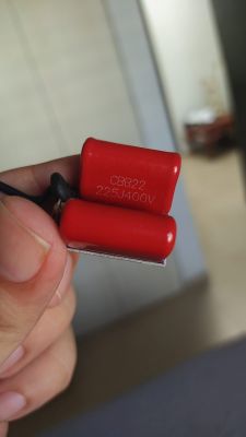
    Make any smart relay no-neutral?. Explanation Make any smart relay no-neutral?. Explanation Make any smart relay no-neutral?. Explanation

    Basically, these are two 2.2 uF in parallel connected to the resistors which appear to be in series with each connection.
  • Helpful post
    #11 20634347
    spin55
    Level 17  
    Hello. If you really want to understand why capacitors are used instead of resistors in alternating current (AC) electric circuits, it's best to familiarize yourself with the basics. This link will help you understand it better than I would if I tried to explain it.

    https://www.youtube.com/watch?v=J8lNkVzukSM

    Roughly speaking, capacitors are used instead of resistors in AC circuits because they are much more efficient. NTC-type resistors are often used to limit the maximum current peaks that can appear at the time of connection to the network, and the resistors that go in parallel with the capacitors are so that they discharge quickly after disconnection and avoid a shock by touching them. They are protective elements.

    The capacitance values ​​of the capacitor/capacitors are related to the current that the circuit has to supply, and the voltage values ​​to the maximum peak voltage value that it has to withstand. Keep in mind that although the effective value of the mains voltage is 230V/50Hz (in my country, for example), the maximum value it will reach will be 230x1'44 (square root of 2) = 325V.

    Grettings
  • #12 20634437
    dead2112
    Level 5  
    Thanks for the reply and the video, it explains very well the reasons of the resistor in parallel.

    One could easily just use a capacitor without the resistance in parallel, but it will imply safety risk of discharge. This is what I've seen in cheaper no-neutral smart switches, they just ship a capacitor.

    Best regards.

    EDIT: I came across to this video for a full no-neutral use with sonoff minr2.
    https://www.youtube.com/watch?v=oBR5O391m_c
  • #13 20635629
    spin55
    Level 17  
    Hello.

    Interesting link, but if you want to put it into practice it is highly recommended that you follow the author's instructions regarding security measures. I am referring to the test with an incandescent lamp connected in series with the circuit to prevent the circuit breaker of the electrical installation from tripping in the event of a short circuit caused by an error in the placement of the components.

    The use of the 10 ohm resistor should not be optional because if we take a look at the datasheet of the 1N4007 diode we see that the maximum peak current it can withstand is 30 amps for a maximum of 8.3 milliseconds.

    Make any smart relay no-neutral?. Explanation

    In my humble opinion, resistance should be an obligation, not an option as it seems to be interpreted from the video display.

    For a network voltage of 230V/50Hz we know that the maximum value is about 325V and that this maximum occurs in half the duration of a half cycle, which is 10 milliseconds. Therefore, that maximum peak will never last more than 8.3 milliseconds. To calculate the minimum value of resistance, divide the (325-1) = 324V by the 30A that the datasheet says that it is capable of withstanding and we have an approximate theoretical value of 10.8 ohms.

    This maximum current spike only occurs when the capacitor is fully discharged. Once it has been uploaded, the datasheet says that the current that the diode can withstand is 1A.

    If for any reason the diode were short-circuited, during the negative half cycle of the wave the polarity applied to the electrolytic capacitor would be reversed and it would explode. Therefore, it is very important not to exceed the limits set by the manufacturer.

    You have to know that the mains voltage has the form of a sine wave and its value is continuously varying between a maximum value of 325V and a minimum value of -325V. At the moment you plug into the network or the relay is closed, you will not be able to know what instantaneous value the voltage is. In this case, the dangerous moment is the maximum positive value of +325V because it is when the diode conducts and has to withstand a voltage at the ends of 324V (325 of the maximum wave minus 1V that falls on the diode when it conducts). That's why the resistor is put in, to limit the maximum instantaneous current specified in the datasheet. If you don't put resistance, the maximum theoretical value that this current peak could reach would be determined by the value in ohms of the resistance of the copper traces, cables and contacts of the relay, which would be a very low value. Assuming it was 1 ohm, the peak current could reach 324A (325-1/1)(Ohm's Law: V=I*R).

    Greetings
  • #14 20636045
    dead2112
    Level 5  
    I do completely agree.

    Looking at the Sonoff zbmini l2, it does not come with a capacitor and it does not induce flickering to the lights, do you know why?
  • #15 20636128
    spin55
    Level 17  
    If that Sonoff was designed to be powered with a single phase without neutral, it is assumed that the internal electrical design is different. It probably doesn't blink because internally it's designed not to. It would be interesting to get the electrical schematic and try to analyze it.

    If you could fit those external components inside the box it wouldn't make a difference visually. Surely there would be internally, without a doubt, but that is another story.

    The assemblies described in the videos are adaptations that are made to adapt a generic device of any brand that needs Phase and Neutral to work, but since only Phase reaches the wall switch, you have to add extra external components to get it to do so .

Topic summary

The discussion revolves around modifying smart relays to function without a neutral wire, particularly focusing on the Sonoff brand. Users share experiences with various configurations, including the use of diodes and capacitors to prevent flickering in lights when the switch is open. The conversation highlights the importance of using protective components like resistors in parallel with capacitors for safety and efficiency in AC circuits. Users also discuss the compatibility of these modifications with two-way switches and the implications of using different capacitance values in the circuit design.
Summary generated by the language model.
ADVERTISEMENT