logo elektroda
logo elektroda
X
logo elektroda

Modifying Tuya Mini for No-Neutral Installation: Experiences with Diode Polarity Reversal?

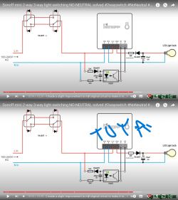
ferbulous 14454 63
Best answers

How can I wire a Tuya/Aubess mini relay for no-neutral operation so the wall switch on S1/S2 still toggles the relay without the module going offline?

Yes, but the thread says your current polarity change is not enough: with that configuration T1 stays on and S1-S2 stay closed, so you need to reorient D5, C1 and D6 so T1 turns off and S1-S2 open when SW1 is open [#20529187] The practical consequence of the simpler diode reversal is that the mini works, but it loses connection when the wall switch is off; in that setup you only get remote control when the wall switch is closed [#20526471] The switch input also needs to be configured in Toggle mode for S2 [#20523207] After the final reconfiguration, spin55 reported that “it works with this assembly,” and the original poster confirmed the working diagram [#20531832]
AI summary based on the discussion. May contain errors.
ADVERTISEMENT
  • Wall switch still cannot toggle relay on Tuya Mini

    #1 20521303
    ferbulous
    Level 18  
    Posts: 419
    Help: 8
    Rate: 56
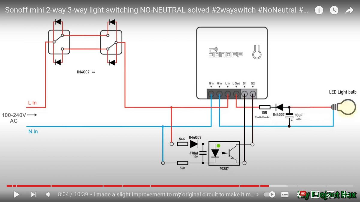
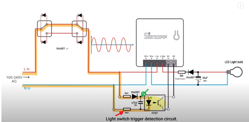
    Has anyone tried this no neutral hack that allows to install the tuya mini on the light fixture?
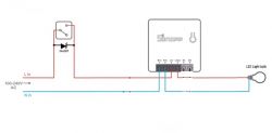
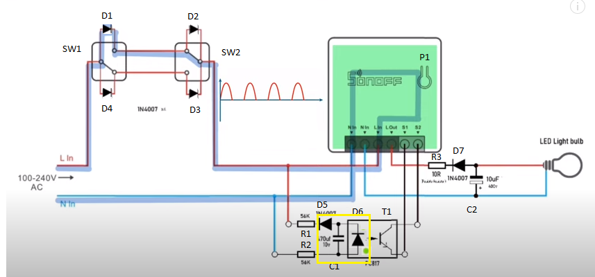
    I had the diodes polarity reversed to get it working with the tuya/aubess, but I still can't toggle the relay from the wall switch (S1 & S2)


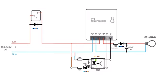
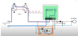
    Modifying Tuya Mini for No-Neutral Installation: Experiences with Diode Polarity Reversal?

    Was wondering if anyone else got it working
  • ADVERTISEMENT
  • #2 20521660
    spin55
    Level 17  
    Posts: 209
    Help: 17
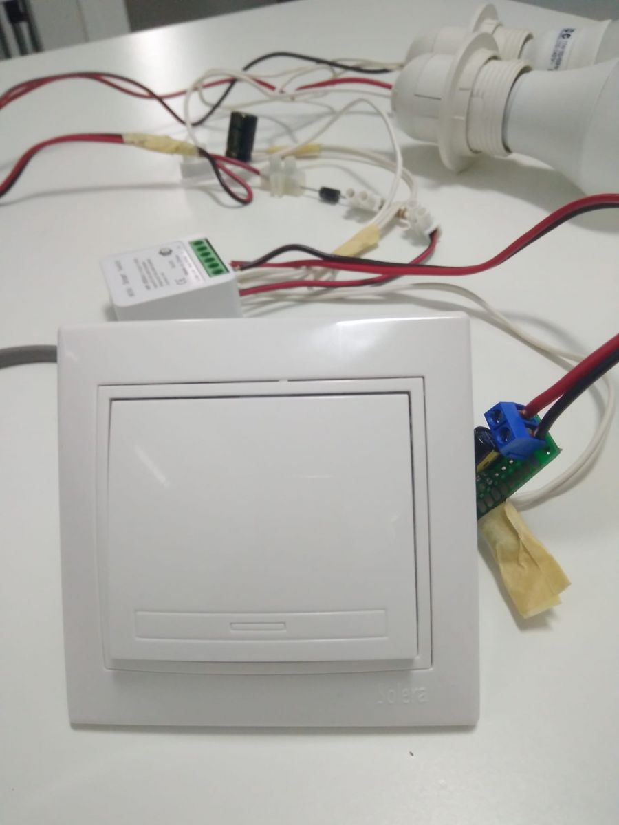
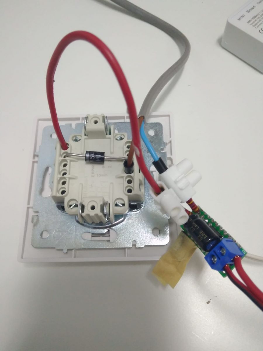
    Rate: 42
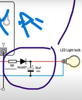
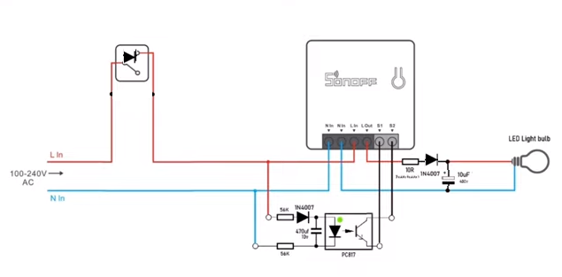
    Have you tried flipping the 1N4007 diode and the 10uF/400V electrolytic capacitor?
  • #3 20521680
    p.kaczmarek2
    Moderator Smart Home
    Posts: 14743
    Help: 659
    Rate: 12839
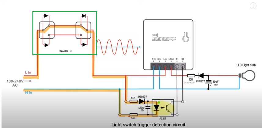
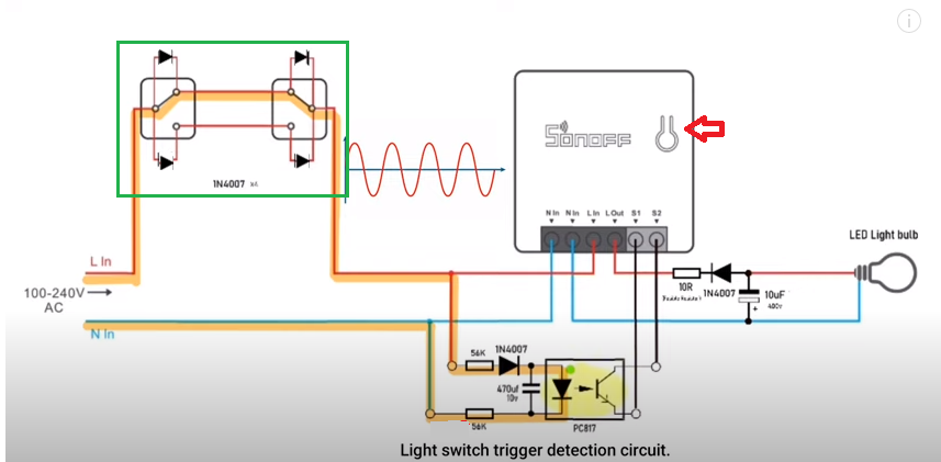
    The trick from video really could work but I am not sure if such a big interference into your electrical wiring is a good and safe idea.
    Helpful post? Buy me a coffee.
  • ADVERTISEMENT
  • #4 20521955
    spin55
    Level 17  
    Posts: 209
    Help: 17
    Rate: 42
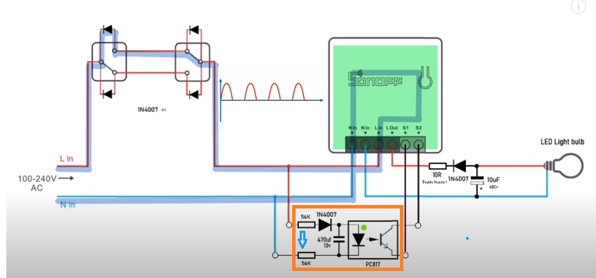
    I think that in addition to the parts that I mentioned before, I would also invert the capacitor and diode that go to the optocoupler so that the internal diode conducts in the positive half cycle of the wave and closes contacts S1 and S2.
    Very good video, although I had not seen it when I answered before.

    Greetings
  • Fusible resistors recommended for added safety

    #5 20522181
    ferbulous
    Level 18  
    Posts: 419
    Help: 8
    Rate: 56
    spin55 wrote:
    I think that in addition to the parts that I mentioned before, I would also invert the capacitor and diode that go to the optocoupler so that the internal diode conducts in the positive half cycle of the wave and closes contacts S1 and S2.
    Very good video, although I had not seen it when I answered before.

    Greetings


    Modifying Tuya Mini for No-Neutral Installation: Experiences with Diode Polarity Reversal?

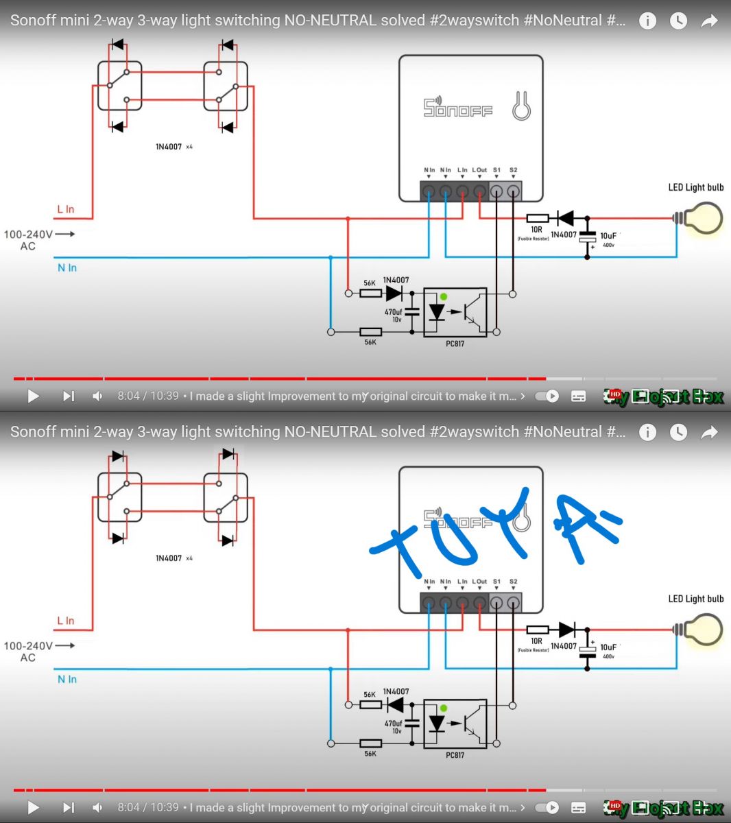
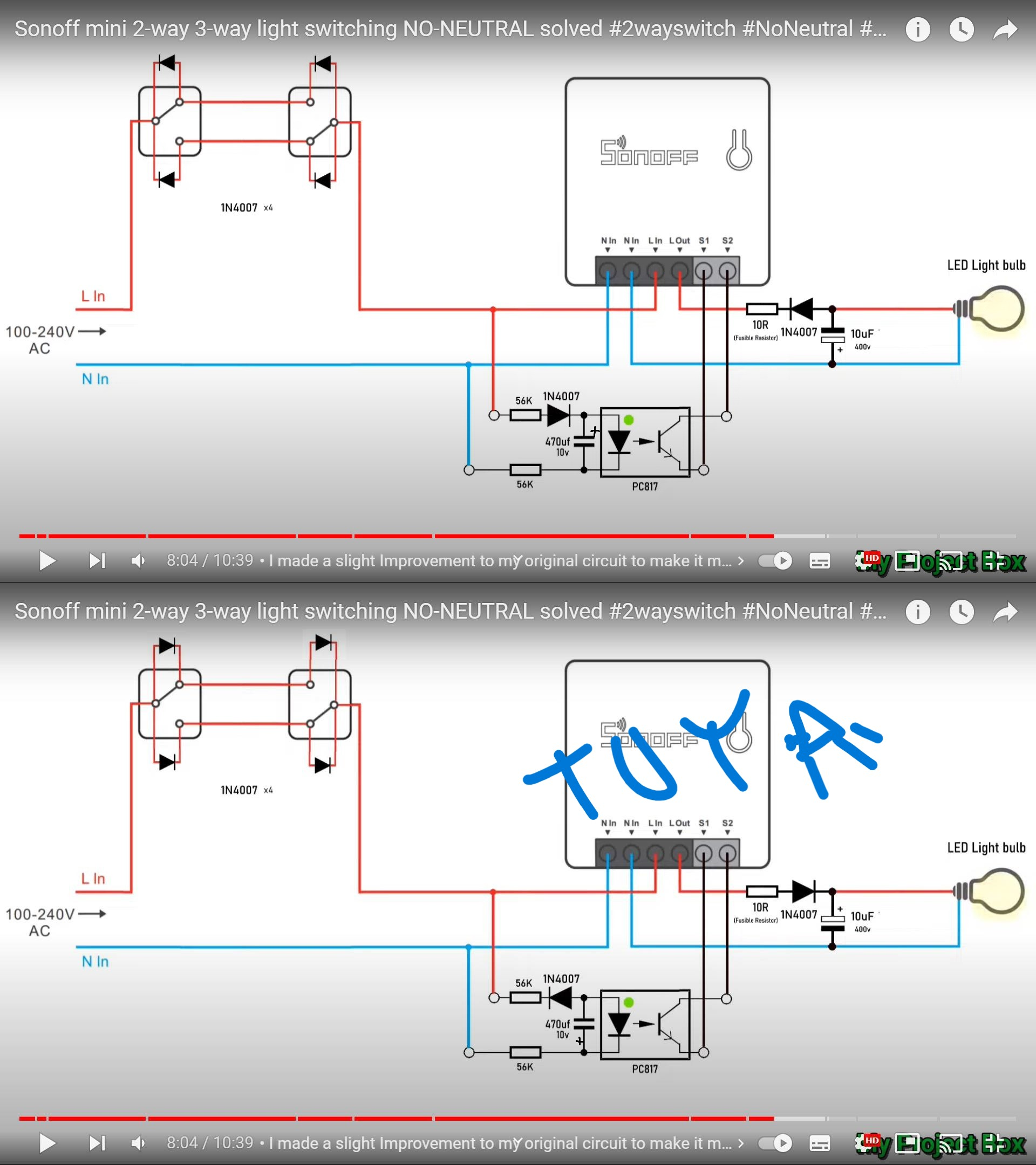
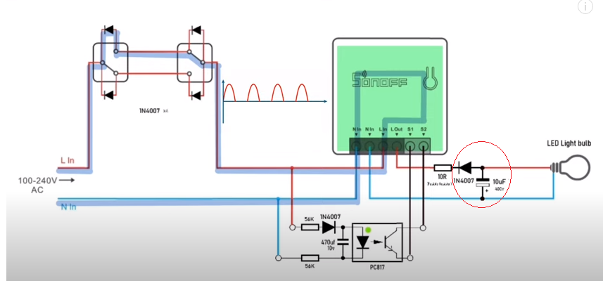
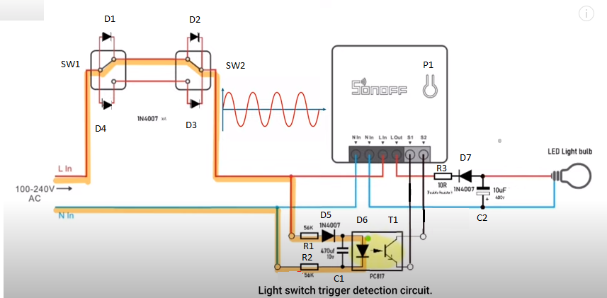
    Ah yes, I did flip those as well. If i’m doing it right on the bottom diagram
    Maybe there's more modification i need to add?

    Added after 2 [minutes]:

    p.kaczmarek2 wrote:
    The trick from video really could work but I am not sure if such a big interference into your electrical wiring is a good and safe idea.


    Any more safety measures that could be added to the circuit?
    The uploader did emphasize on using fusible resistors for safety reason
  • Need to invert diode and capacitor polarity for half-wave operation

    #6 20522303
    spin55
    Level 17  
    Posts: 209
    Help: 17
    Rate: 42
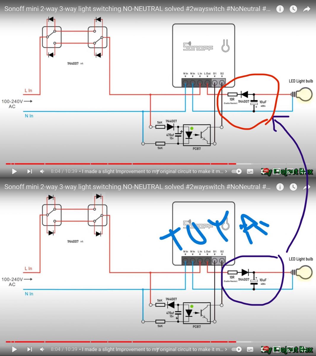
    In the image above it has a good diode, capacitor and optocoupler, but you would also need to invert the diode and capacitor of the bulb part so that everything works in the positive half-wave of the mains voltage. Actually it would be enough to exchange the inputs to the diode of the optocoupler and I think it would work with the original circuit and negative half wave. But I guess it's better to flip capacitors and diodes than cut leads if you already have the board done.

    The bottom image does not work because you would have to flip the diode and capacitor to work with a positive half wave and correctly bias the internal diode of the optocoupler.


    Greetings
  • Reverse bulb-side diode and capacitor polarity

    #7 20522314
    ferbulous
    Level 18  
    Posts: 419
    Help: 8
    Rate: 56
    spin55 wrote:
    In the image above it has a good diode, capacitor and optocoupler, but you would also need to invert the diode and capacitor of the bulb part so that everything works in the positive half-wave of the mains voltage. Actually it would be enough to exchange the inputs to the diode of the optocoupler and I think it would work with the original circuit and negative half wave. But I guess it's better to flip capacitors and diodes than cut leads if you already have the board done.

    The bottom image does not work because you would have to flip the diode and capacitor to work with a positive half wave and correctly bias the internal diode of the optocoupler.


    Greetings


    Just to clarify, i would just need to change diode & capacitor poles to the bulbs back to the orignal arrangement with the sonoff?

    Modifying Tuya Mini for No-Neutral Installation: Experiences with Diode Polarity Reversal?
  • #8 20522316
    spin55
    Level 17  
    Posts: 209
    Help: 17
    Rate: 42
    That is.
  • Wall switch only works when relay is on

    #9 20522319
    ferbulous
    Level 18  
    Posts: 419
    Help: 8
    Rate: 56
    spin55 wrote:
    That is.


    Noted, will try that
    On my 1st attempt using the sonoff arrangement. The tuya mini switch didn’t boot up at all which is why i reversed the poles

    Added after 7 [hours] 33 [minutes]:

    @spin55
    hi, some update

    Modifying Tuya Mini for No-Neutral Installation: Experiences with Diode Polarity Reversal?

    With this arrangement, I can toggle from the wall switch but only if the relay is turned on. If relay is turned off, I can't trigger it from the switch
  • ADVERTISEMENT
  • Check Sonoff online state and RC values first

    #10 20523207
    spin55
    Level 17  
    Posts: 209
    Help: 17
    Rate: 42
    First clarify that I have not experimented with this assembly. All I tell you is based on what I see on the electrical diagram.

    Checks to perform:
    1.- Sonoff stays online when you turn off a key?
    2.- If positive, if the relay does not hold until the next half wave, you will have to play with the values ​​of the RC network of the optocoupler. But first try to change the 56K resistor that goes to the cathode of the optocoupler diode for another 100K, or higher depending on the result.
    If that causes the LED not to activate, I would try inserting a resistor between the capacitor and the anode of the optocoupler.

    Modifying Tuya Mini for No-Neutral Installation: Experiences with Diode Polarity Reversal?

    Added after 11 [minutes]:

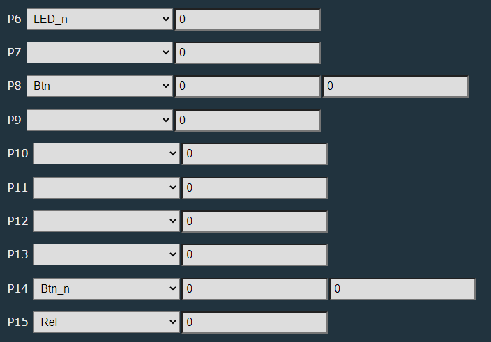
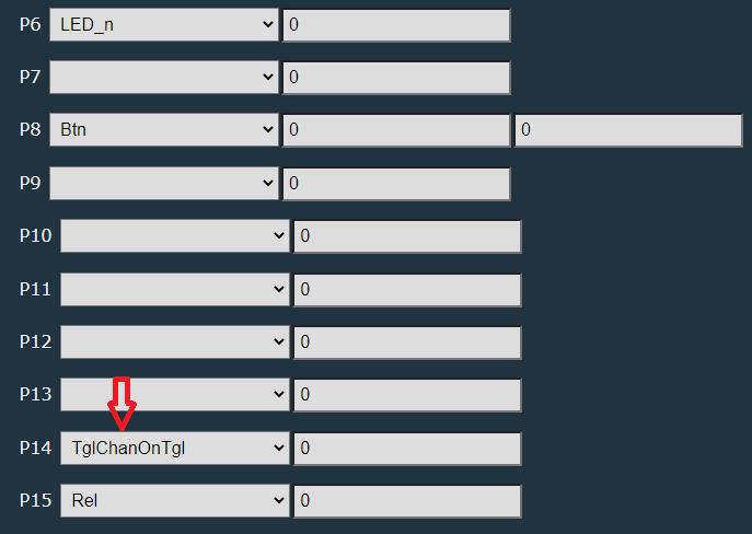
    How do you have S2 configured in Sonoff? It would have to be in Toggle mode for it to maintain the connection.
    First check that Sonoff is still online when you turn off a key before you start changing resistors.
  • Toggle mode and 100 kΩ resistor suggested for S2 hold-up

    #11 20524259
    ferbulous
    Level 18  
    Posts: 419
    Help: 8
    Rate: 56
    spin55 wrote:
    First clarify that I have not experimented with this assembly. All I tell you is based on what I see on the electrical diagram.

    Checks to perform:
    1.- Sonoff stays online when you turn off a key?
    2.- If positive, if the relay does not hold until the next half wave, you will have to play with the values ​​of the RC network of the optocoupler. But first try to change the 56K resistor that goes to the cathode of the optocoupler diode for another 100K, or higher depending on the result.
    If that causes the LED not to activate, I would try inserting a resistor between the capacitor and the anode of the optocoupler.

    Modifying Tuya Mini for No-Neutral Installation: Experiences with Diode Polarity Reversal?

    Added after 11 [minutes]:

    How do you have S2 configured in Sonoff? It would have to be in Toggle mode for it to maintain the connection.
    First check that Sonoff is still online when you turn off a key before you start changing resistors.


    1) yes, it stays online
    2) i will update later today once i get home and retry with higher resistors.

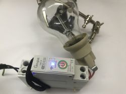
    Video demo, please ignore the fluorescent bulb


    3) yes, i have setup the pin as toggleonchannel
  • #12 20524329
    spin55
    Level 17  
    Posts: 209
    Help: 17
    Rate: 42
    Just to confirm. Have you changed that or have you left it as the original?

    Modifying Tuya Mini for No-Neutral Installation: Experiences with Diode Polarity Reversal? Modifying Tuya Mini for No-Neutral Installation: Experiences with Diode Polarity Reversal?

    Added after 11 [minutes]:

    ferbulous wrote:
    2) i will update later today once i get home and retry with higher resistors.


    Don't make those changes for now.
  • #13 20524589
    ferbulous
    Level 18  
    Posts: 419
    Help: 8
    Rate: 56
    @spin55
    I’ve reverted back to the original diagram (except for the diode on the wall switch that must be reversed for tuya mini to work)
  • #14 20524600
    spin55
    Level 17  
    Posts: 209
    Help: 17
    Rate: 42
    What pin configuration do you have? Are S2 and mini push button on the same channel?
    Modifying Tuya Mini for No-Neutral Installation: Experiences with Diode Polarity Reversal?
  • #15 20525635
    ferbulous
    Level 18  
    Posts: 419
    Help: 8
    Rate: 56
    spin55 wrote:
    What pin configuration do you have? Are S2 and mini push button on the same channel?
    Modifying Tuya Mini for No-Neutral Installation: Experiences with Diode Polarity Reversal?


    Yes, all on the same channel
    I’ve also changed the S2 (pin 14) to both toggleonchannel & btn_n with the same result
  • ADVERTISEMENT
  • #16 20525679
    spin55
    Level 17  
    Posts: 209
    Help: 17
    Rate: 42
    This is the configuration you have, right? Now I have to go out, I'll take the opportunity to buy a wall switch and I'll do some tests with my mini-switch. I'll inform you.

    Modifying Tuya Mini for No-Neutral Installation: Experiences with Diode Polarity Reversal?
  • Tuya wall switch wiring follows Sonoff Switchman diagram

    #17 20525854
    ferbulous
    Level 18  
    Posts: 419
    Help: 8
    Rate: 56
    spin55 wrote:
    This is the configuration you have, right? Now I have to go out, I'll take the opportunity to buy a wall switch and I'll do some tests with my mini-switch. I'll inform you.

    Modifying Tuya Mini for No-Neutral Installation: Experiences with Diode Polarity Reversal?


    Correct, that's what I ended up with after not much difference between changing the polarity for the diode next to the octocoupler.

    Thanks for testing it out, i hope you find a solution for this

    If you have tuya wifi/zigbee wall switch you can follow the same wiring diagram for the sonoff switchman. Zigbee switch will still act as repeaters


  • #18 20526312
    spin55
    Level 17  
    Posts: 209
    Help: 17
    Rate: 42
    Can you confirm if the led of the "Sonoff" button changes when you turn the wall switch on and off? It doesn't look good on the video.

    Modifying Tuya Mini for No-Neutral Installation: Experiences with Diode Polarity Reversal?
  • Wall switch toggles bulb but not relay

    #19 20526372
    ferbulous
    Level 18  
    Posts: 419
    Help: 8
    Rate: 56
    @spin55
    For the tuya wifi mini

    Relay on (via openbk ui or small button)

    Wall switch toggle on led onlight bulb on
    Wall switch toggle off led onlight bulb off


    Relay off (via openbk ui or small button)

    Wall switch toggle onled off light bulb off
    Wall switch toggle off led off light bulb off


    Another scenario, if the light bulb was already off before the relay is toggled off.
    When the relay is turned on, light bulb stays off and i’ll need to toggle the wall switch again to turn light bulb on

    So toggling switch only toggles the light bulb but not the relay, and the relay has to be on to work.
  • Diode reversal trades remote uptime for wall-switch control

    #20 20526471
    spin55
    Level 17  
    Posts: 209
    Help: 17
    Rate: 42
    Do what it shows in the video. When you open the relay with a push button and the bulb no longer turns on when you press the wall switch, short-circuit S1 and S2 and tell me what happens.

    Added after 2 [minutes]:

    ferbulous wrote:
    So toggling switch only toggles the light bulb but not the relay, and the relay has to be on to work.


    By shorting S1 and S2 we will see if the relay is activated or not.

    Momentary short circuit, do not hold.

    Added after 25 [minutes]:

    If the relay is activated by short-circuiting momentarily, the RC value of the trigger must be decreased. Either by reducing the value of the 56K resistor or the 470uF capacitor, so that the optocoupler LED turns off during the negative half cycle of the wave.
    Modifying Tuya Mini for No-Neutral Installation: Experiences with Diode Polarity Reversal?

    Added after 1 [hours] 15 [minutes]:

    This is the setup I've tried.

    Modifying Tuya Mini for No-Neutral Installation: Experiences with Diode Polarity Reversal?

    With the diode in that position, Sonoff stays online both when I turn the wall switch ON and OFF.
    In the OFF position, the bulb blinks, but that is logical because it only works with half wave. It is corrected with capacitor and diode.
    But there is a big problem: You can't control the bulb with the wall switch, it only supports remote control via web.
    So you have to add the trigger circuit to be able to control the bulb via S1-S2. I haven't been able to do this test because I don't have an optocoupler.
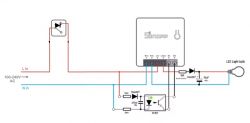
    Modifying Tuya Mini for No-Neutral Installation: Experiences with Diode Polarity Reversal?

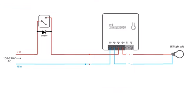
    If I reverse the position of the diode, everything works like the classic series assembly where the power to Sonoff is provided through the wall switch in the ON position. So it can be controlled remotely, but when the switch turns OFF, Sonoff loses connection. In this way you have manual control of turning the bulb on and off, but remotely only if the wall switch is ON. That's how I've had it so far and it's fine for me.

    Greetings
  • Diode reversal restores classic series switching

    #21 20527321
    ferbulous
    Level 18  
    Posts: 419
    Help: 8
    Rate: 56
    spin55 wrote:
    By shorting S1 and S2 we will see if the relay is activated or not.

    Ok, how do I short S1 & S2?

    spin55 wrote:
    So you have to add the trigger circuit to be able to control the bulb via S1-S2. I haven't been able to do this test because I don't have an optocoupler.

    With the added octocoupler, this is what I'm getting now

    ferbulous wrote:


    Wall switch toggle onled off light bulb on
    Wall switch toggle off led off light bulb off


    Another scenario, if the light bulb was already off before the relay is toggled off.
    When the relay is turned on, light bulb stays off and i’ll need to toggle the wall switch again to turn light bulb on


    spin55 wrote:
    If I reverse the position of the diode, everything works like the classic series assembly where the power to Sonoff is provided through the wall switch in the ON position. So it can be controlled remotely, but when the switch turns OFF, Sonoff loses connection. In this way you have manual control of turning the bulb on and off, but remotely only if the wall switch is ON. That's how I've had it so far and it's fine for me.

    I'm trying to avoid this because there would be no point of doing it if sonoff goes offline when wall switch is toggled off
  • Short S1 and S2 to test relay switching

    #22 20527496
    spin55
    Level 17  
    Posts: 209
    Help: 17
    Rate: 42
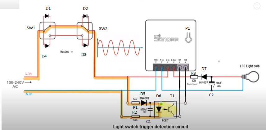
    To understand us better, we are going to take this diagram as a reference:

    Modifying Tuya Mini for No-Neutral Installation: Experiences with Diode Polarity Reversal?

    Ok, how do I short S1 & S2?

    When you turn off the relay with P1 and can no longer turn on/off with SW1 or SW2, please take a piece of wire and touch both ends S1 and S2 at the same time and remove. Change the relay?

    With the added octocoupler, this is what I'm getting now

    We'll talk about that later. First you have to check if the relay changes with a short circuit of S1 and S2.
  • #23 20527785
    ferbulous
    Level 18  
    Posts: 419
    Help: 8
    Rate: 56
    @spin55
    Would i need to remove the cables from the octocoupler to S1 & S2 before shorting it?
  • #24 20527813
    spin55
    Level 17  
    Posts: 209
    Help: 17
    Rate: 42
    For this test do not remove them.

    Added after 8 [minutes]:

    If the relay does not switch, disconnect S1 and S2 from the optocoupler and repeat the operation.
  • #25 20529187
    spin55
    Level 17  
    Posts: 209
    Help: 17
    Rate: 42
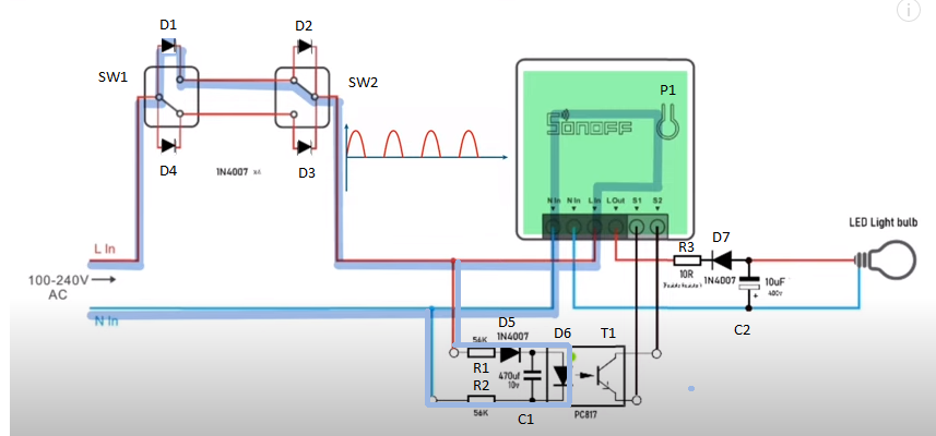
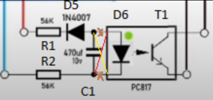
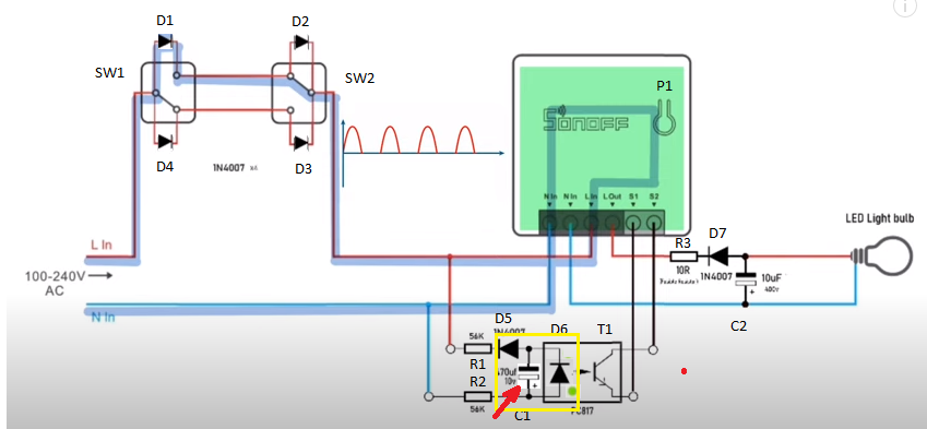
    With the current configuration this will not work because T1 is always ON and S1-S2 Close when SW1 is Open or Close.

    Modifying Tuya Mini for No-Neutral Installation: Experiences with Diode Polarity Reversal?
    Modifying Tuya Mini for No-Neutral Installation: Experiences with Diode Polarity Reversal?

    You have to turn D5, C1 and D6 to make T1 OFF and S1-S2 Open when SW1 is Open .

    Modifying Tuya Mini for No-Neutral Installation: Experiences with Diode Polarity Reversal?
  • #26 20529201
    ferbulous
    Level 18  
    Posts: 419
    Help: 8
    Rate: 56
    @spin55 I’m not home yet for now to test it
    For the 3rd pic, how do i reverse the D6 (diode) since it’s part of the octocoupler? T1 as well?
    ————————
    Nevermind, I’ll just need to swap the L & N connection to the octocoupler
  • #27 20530029
    spin55
    Level 17  
    Posts: 209
    Help: 17
    Rate: 42
    ferbulous wrote:
    For the 3rd pic, how do i reverse the D6 (diode) since it’s part of the octocoupler? T1 as well?


    Modifying Tuya Mini for No-Neutral Installation: Experiences with Diode Polarity Reversal?

    Added after 10 [hours] 26 [minutes]:

    Beware of this if C1 has polarity!.

    Modifying Tuya Mini for No-Neutral Installation: Experiences with Diode Polarity Reversal?
  • Helpful post

    Working Tuya Mini wiring configuration confirmed

    #28 20531832
    spin55
    Level 17  
    Posts: 209
    Help: 17
    Rate: 42
    And configure like this:
    Modifying Tuya Mini for No-Neutral Installation: Experiences with Diode Polarity Reversal?

    Added after 6 [hours] 8 [minutes]:

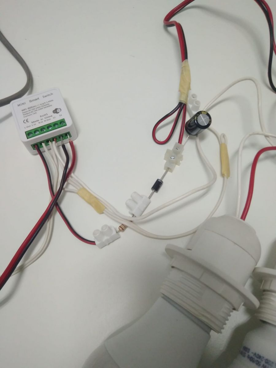
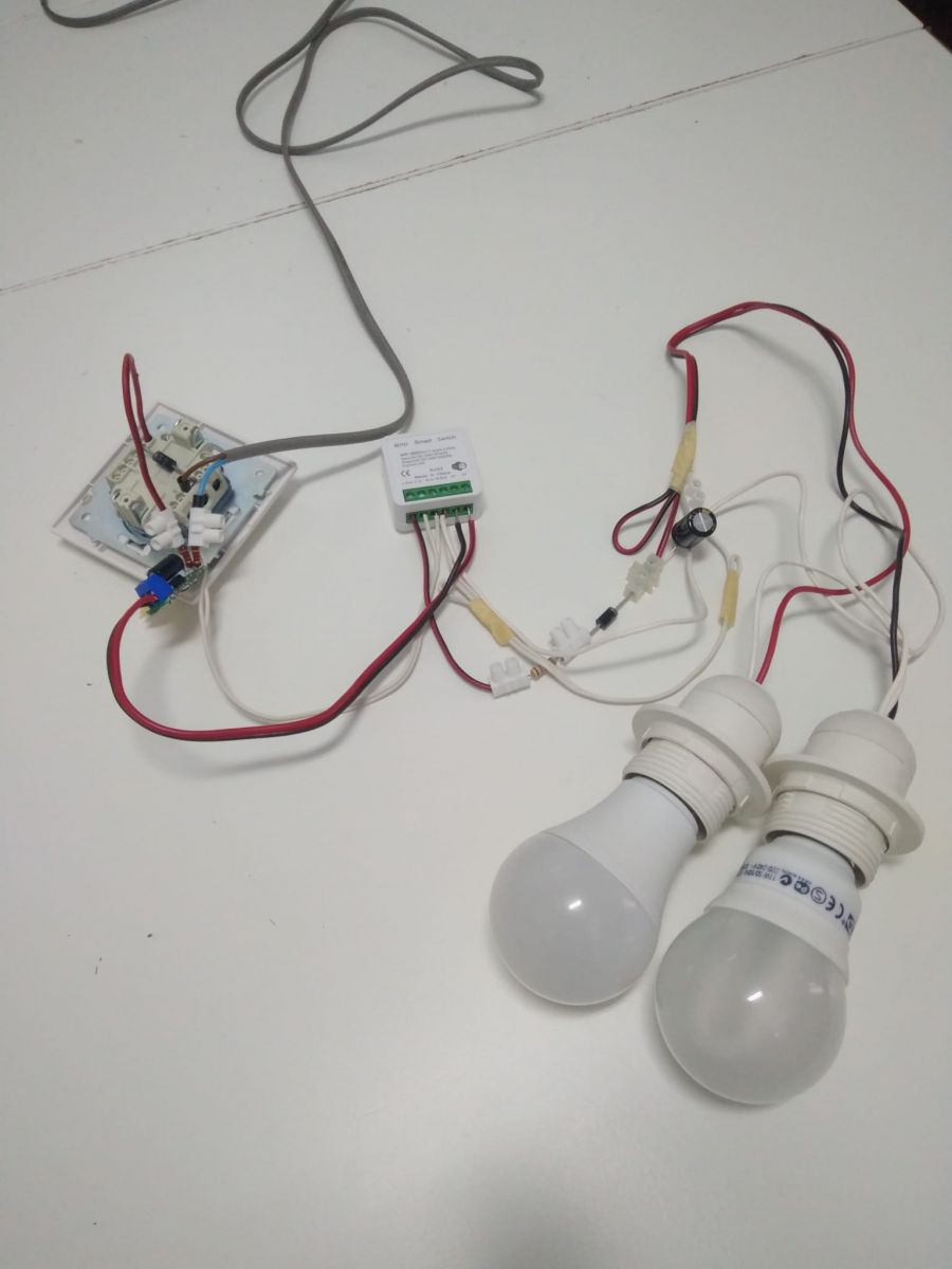
    It works with this assembly:
    Modifying Tuya Mini for No-Neutral Installation: Experiences with Diode Polarity Reversal?

    Added after 1 [hours] 9 [minutes]:


    Modifying Tuya Mini for No-Neutral Installation: Experiences with Diode Polarity Reversal? Modifying Tuya Mini for No-Neutral Installation: Experiences with Diode Polarity Reversal? Modifying Tuya Mini for No-Neutral Installation: Experiences with Diode Polarity Reversal? Modifying Tuya Mini for No-Neutral Installation: Experiences with Diode Polarity Reversal?
  • #29 20534324
    ferbulous
    Level 18  
    Posts: 419
    Help: 8
    Rate: 56
    @spin55 thanks for the successful test & the working diagram!
    I think I’ll move to using cables this time instead of pcb and redo this again
  • #30 20534335
    p.kaczmarek2
    Moderator Smart Home
    Posts: 14743
    Help: 659
    Rate: 12839
    @spin55 very good job, you should post it separately to Smart Home Tutorials section with a better description (in a form of tutorial) and get a free gift:
    https://www.elektroda.com/rtvforum/topic3950844.html
    Helpful post? Buy me a coffee.

Topic summary

✨ The discussion centers on modifying Tuya Mini and similar smart switches (e.g., Aubess mini, Sonoff Mini-R2) for no-neutral wire installations by reversing diode polarity and adjusting associated components. Key modifications include flipping the 1N4007 diodes and electrolytic capacitors, especially those connected to the optocoupler, to ensure conduction during the positive half-wave of the AC mains. The relay toggle functionality from wall switches (S1 & S2) is problematic when the relay is off, requiring further circuit tuning such as adjusting RC network resistor values (e.g., increasing from 56K to 100K) to maintain relay activation. Safety improvements involve using fusible resistors placed near capacitors to handle inrush currents during capacitor charging. The no-neutral hack is effective for lighting loads but may not suit AC motors or fans due to half-wave DC supply potentially damaging motor windings; DC fans may work if diode ratings and capacitor values are adjusted accordingly. Testing with loads like hand dryers confirmed AC devices fail to operate properly on half-wave DC. The community shared detailed wiring diagrams, component value calculations, and practical test results, including current through optocoupler LEDs (~1.14 mA) and resistor power dissipation estimates. The discussion also covers alternative wiring setups with neutral at the ceiling, remote control integration, and the impact of switch configurations on relay behavior. The original no-neutral circuit author offered to provide updated designs and tutorials. Overall, the thread provides a comprehensive technical exploration of no-neutral smart switch modifications, component selection, safety considerations, and load compatibility.
AI summary based on the discussion. May contain errors.

FAQ

TL;DR: For 230 V, 50 Hz Tuya/Aubess no-neutral installs, the tested fix is “It works with this assembly”: align diode/capacitor polarity with the mini switch, add an optocoupler trigger, and keep the load circuit protected by a fusible resistor. This FAQ is for smart-switch modders solving S1/S2 relay-toggle failure at the light fixture. [#20531832] Why it matters: A wrong half-wave polarity can keep the module online while leaving the wall switch unable to toggle the relay.

Alternative Result in the thread Practical limit
Sonoff-style original polarity Tuya Mini did not boot on the first attempt Needs polarity adaptation
Reversed diode for Tuya/Aubess Mini switch powered on S1/S2 trigger still needed
Tested optocoupler assembly Wall switch and remote control worked Requires careful mains wiring
Simple series wiring Manual works; remote works only with switch ON Module goes offline when switch OFF

Key insight: The Tuya/Aubess version is not just a diode swap. The optocoupler trigger must open and close S1/S2 at the correct half-cycle, while the mini switch stays powered.

Quick Facts

  • The tested optocoupler input used measured resistors of 45.9 kΩ and 46.9 kΩ, with 1.1 Vdc on C1 and 1.14 mA current. [#21406579]
  • At 236 Vac mains, the peak voltage was calculated as 332 Vac, and Vdc was estimated as Vp/π, or 105.73 Vdc. [#21406579]
  • A 10 Ω fusible resistor at 50 W and 230 V with cos φ = 1 dissipates about 0.515 W, so a 1 W part was suggested. [#20772829]
  • The bulb-side capacitor was discussed as 400 V, and one tested fan/load circuit used C2 = 470 µF / 450 V. [#20540862]
  • For 50 Hz mains, the capacitor near the bulb bridges the 10 ms negative half-cycle to reduce visible flicker. [#20746946]

How can I modify a Tuya or Aubess mini switch for a no-neutral installation at the light fixture?

Use the tested Tuya/Aubess adaptation with a series diode, bulb-side smoothing parts, and an optocoupler trigger for S1/S2.
  1. Find the diode polarity that powers the mini switch.
  2. Build the rest of the half-wave circuit to that polarity.
  3. Add the optocoupler circuit so the wall switch pulses S1/S2. One user later confirmed the idea worked on Aubess mini switches. [#20745181]

Why does reversing the diode polarity make a Tuya Mini boot in a no-neutral circuit but stop S1 and S2 from toggling the relay?

Reversing only the power diode can feed the Tuya Mini but leave the optocoupler biased wrong. In that state, the wall switch changes the bulb path, not the relay input. The reported failure was precise: relay ON allowed bulb control, but relay OFF blocked wall-switch triggering. The trigger transistor stayed in the wrong state until D5, C1, and D6 were turned. [#20529187]

Which diodes and capacitors need to be flipped when adapting the Sonoff Mini R2 no-neutral hack for a Tuya or Aubess mini switch?

Flip the diode and capacitor around the bulb path, plus the optocoupler-side polarity parts. The thread specifically named D5, C1, and D6 for correction, so T1 turns OFF and S1/S2 opens when SW1 opens. If C1 is polarized, its polarity matters because reversing it incorrectly can damage the capacitor. [#20530029]

How do I test whether shorting S1 and S2 manually will trigger the relay in a modified Tuya Mini no-neutral setup?

Momentarily bridge S1 and S2 with a wire after the relay is turned off by the module button. Do not hold the short. First test with the optocoupler still connected. If the relay does not switch, disconnect S1 and S2 from the optocoupler, then repeat the momentary bridge. This separates firmware/input failure from trigger-circuit failure. [#20527813]

What OpenBeken pin configuration should I use for S2 on a Tuya Mini when the wall switch should toggle the same relay channel?

Configure S2 on the same relay channel, using Toggle mode or the tested OpenBeken options for that channel. The user had S2 on pin 14 and tested both toggleonchannel and btn_n. The mini push button and S2 were also assigned to the same channel. That setup removed channel mismatch as the main fault. [#20525635]

Why does the wall switch only control the bulb when the Tuya Mini relay is already on in this no-neutral circuit?

The wall switch only controls the bulb because S1/S2 is not receiving a valid trigger pulse. With the relay ON, the bulb path exists, so toggling the wall switch changes the lamp. With the relay OFF, the bulb remains off and the relay never changes state. The thread traced this to an optocoupler trigger state problem, not OpenBeken alone. [#20526372]

What is an optocoupler and why is it used between the wall switch circuit and S1/S2 on a Tuya Mini?

An optocoupler lets the wall-switch half-wave circuit trigger S1/S2 without directly joining the mains-side circuit to the module input. “Optocoupler is an isolation component that transfers a signal using light, keeping input and output electrically separated while allowing a low-current LED side to control a transistor side.” The tested circuit used about 1.14 mA through that input. [#21406579]

What is a fusible resistor and why is it recommended for safety in no-neutral smart switch hacks?

A fusible resistor limits current and opens under fault conditions instead of acting like ordinary wire. “Fusible resistor is a safety resistor that carries normal circuit current, limits surge current, and is designed to fail open during overload, reducing fire risk compared with a standard resistor.” The video author emphasized fusible resistors, and the thread later stated all assemblies need fuse protection. [#20538272]

How do I choose the wattage for a 10 ohm fusible resistor in a no-neutral LED lighting circuit?

Calculate resistor power from lamp current, then add margin for mains tolerance. For a 50 W LED at 230 V and cos φ = 1, current is 0.227 A. A 10 Ω resistor then dissipates 0.515 W. Because mains can vary by ±10%, the suggested practical choice was 1 W or the nearest standard value. [#20772829]

When can I omit the 400V capacitor near the bulb in a no-neutral Tuya Mini or Aubess Mini installation?

You can omit the 400 V capacitor when the bulb does not visibly blink without it. The capacitor exists to keep the lamp on during the negative half-cycle. At 50 Hz, that gap lasts about 10 ms. If the lamp driver hides that flicker, the capacitor is not required and space improves. [#20746946]

Tuya Mini vs Sonoff Mini R2: what changes are needed when using the Sonoff no-neutral circuit on Tuya or Aubess hardware?

Tuya/Aubess hardware needs polarity matched to the module, not copied blindly from Sonoff Mini R2. The first Tuya attempt using the Sonoff arrangement did not boot. Reversing polarity powered the Tuya Mini, then the optocoupler trigger still needed correction. A later practical tip was to start with one series diode in Line In and build the circuit from the working polarity. [#20745181]

Can a no-neutral half-wave circuit safely power a ceiling fan, and how does the answer change for AC motor vs DC motor fans?

Do not run an AC fan motor from the half-wave DC load circuit. The thread warned that motor winding impedance is too small in DC, so damage can occur. A DC fan may work if its internal supply suits the circuit, but the diodes and C2 must match load current and ripple. One discussed fan range was 14.1 W to 82.5 W. [#20536819]

What diode ratings should I use instead of 1N4007 or UF5408 for higher-power loads in a no-neutral smart switch circuit?
Choose diodes by load current and voltage, not by the mini-switch name. The thread used 1N4007 in small tests and UF5408 because those parts were available. For larger loads, select D1 and D7 from the fan or lamp current in amps. One proposed test used UF5408 with C2 = 470 µF / 450 V. [#20540862]

How can I check whether a ceiling fan uses an AC motor or DC motor before connecting it to a half-wave no-neutral circuit?

Use the relay test described in the thread before committing the ceiling fan. With SW1 closed and relay ON by web control, the fan should run normally. Then open SW1 and turn the relay ON by web control. If there is movement in the half-wave state, the fan behaves as a DC fan in that test. [#20542515]

What are the safety risks of building a no-neutral Tuya Mini modification inside a wall box or ceiling fixture?

The risks include mains shock, overheated resistors, damaged capacitors, and damaged AC motor loads. The circuit works directly around 230 Vac mains and peak voltages near 332 Vac were measured. One expert warned that major wiring interference may not be safe. Another warned: “don’t try it” if you do not understand what the circuit does. [#20538272]
AI summary based on the discussion. May contain errors.
ADVERTISEMENT