logo elektroda
logo elektroda
X
logo elektroda

PCF8574 port expander module - PlatformIO tutorial - Arduino/ESP/itd pin expansion

p.kaczmarek2 2175 11
ADVERTISEMENT
Treść została przetłumaczona polish » english Zobacz oryginalną wersję tematu
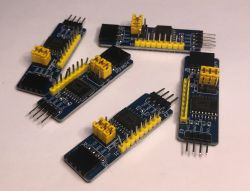
  • Several PCF8574 modules with exposed goldpins .
    Here I will present a simple to use module to get additional I/O ports. One PCF8574 is controlled by only two signals, and gives us as many as 8 configurable I/Os together with an additional optional interrupt signal. What's more, two pins can drive as many as eight PCF8574s simultaneously, giving us a total of 64 pins, and combined with the alternate address version up to 128 pins! It is also worth knowing that nothing prevents other devices, such as sensors or there RTC clock, from being connected together with the PCF8574 on the I2C bus ... but one step at a time.

    The PCF8574 is a so-called IO expander, i.e. a circuit which, when suitably controlled, allows us to obtain additional input/output pins in our project. Specifically, the PCF8574 is controlled via the I2C bus, which is a bus based on two signals (clock and data) and allows us to handle multiple devices simultaneously - multiple chips can be connected to a single I2C line, as long as their addresses do not collide.
    The PCF operates at 2.5 V to 6 V, so there should be no problems running it with either the classic Arduino or the ESP8266.
    Consider the leads of the PCF8574:
    PCF8574 schematic with I2C bus. .
    SDA and SCL are the mandatory I2C lines, this is what we control this chip with. P0-P7 are the legs of the circuit we control, they can be in the role of digital inputs and outputs. Pins A0, A1, A2 allow us to change the address of a given PCF piece, so we can connect more of them on one bus:
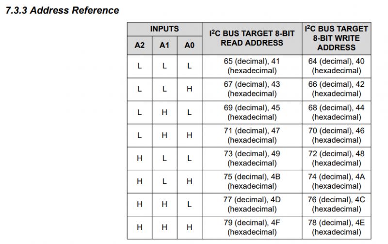
    I2C address table for PCF8574 with inputs A2, A1, A0 settings. .
    The PCF offers four GPIO modes of operation:
    Description of four port operation modes in PCF8574. .
    For more advanced users, it is also useful to provide a more detailed schematic, which also takes into account the line pull-up resistors from I2C:
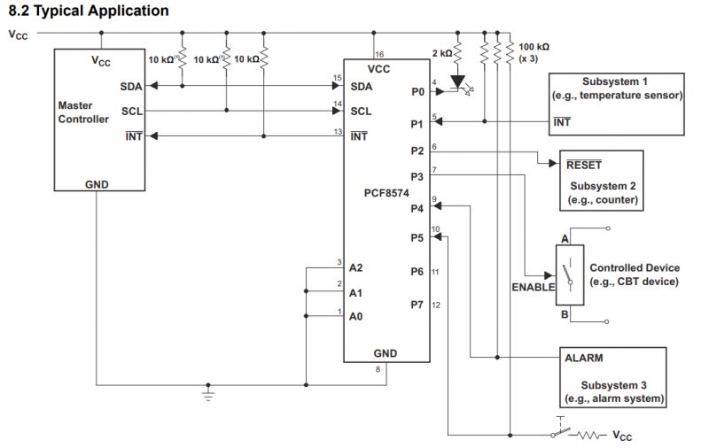
    Diagram of PCF8574 application with connected resistors and devices. .
    Out of curiosity, I should add that the catalogue note also proposes a PCB layout for the expander:
    PCF8574 connection schematic .
    Here, however, I will use a ready-made module, which will simplify everything considerably.


    Module PCF8574 .
    The commercially available PCF8574 module outputs all its legs on goldpins, which relieves us of the need to solder. All IO, interrupt output, address pins and the I2C bus are routed out - and on both sides. The aforementioned pull-up resistors are also on board.
    Several PCF8574 modules with exposed goldpins .
    PCF8574 modules with yellow connectors on a white background .
    PCF8574 modules on prototype boards. .
    You can get the module for a few zlotys. By importing from abroad you can even get 5 pieces for 10-20 PLN, depending on the promotion.
    Image of five PCF8574 modules on a white background. .
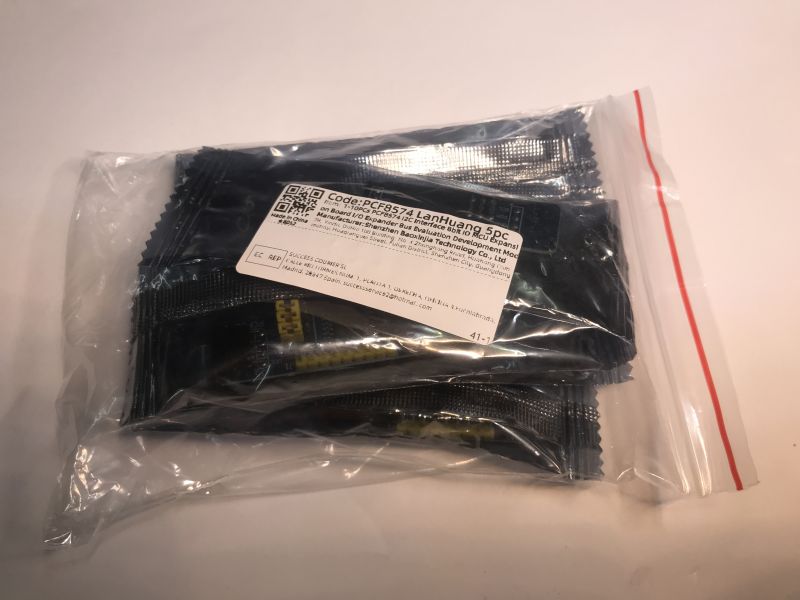
    Set of PCF8574 modules packed in transparent plastic bags. .


    Demonstration platform .
    As a rule, I've done this type of demonstration on an Arduino, but this time I was tempted to use a NodeMCU with an ESP8266. It will come out almost the same anyway, but in my opinion PlatformIO is a bit more convenient than the Arduino IDE, and knowledge of Visual Code is also useful for other languages. Recall the topic where I already presented PlatformIO:
    Clock on ESP12 and MAX7219 display - tutorial - part 1, ArduinoOTA, basics .
    How to program a Wemos D1 (ESP8266) board in the shape of an Arduino? ArduinoOTA in PlatformIO
    Plate used:
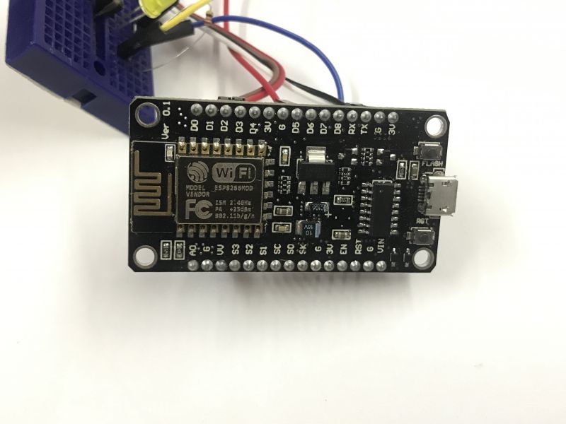
    ESP8266 module connected to a breadboard. .


    I2C scan .
    Using the expander is very straightforward, but users often get lost through the I2C addresses. For this reason I always suggest running an I2C scanner to start with. This simple program will verify our connections and display the I2C addresses of the devices connected to the bus. This will tell us if at least hardware-wise the situation is ok, as it is easy to swap SCL with SDA or connect something wrong....
    Here is my connection:
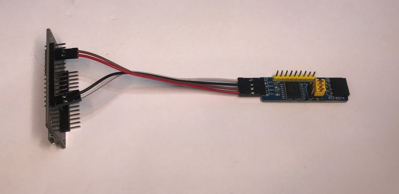
    PCF8574 module with connected wires. .
    Well, and the aforementioned scanner:
    Code: C / C++
    Log in, to see the code
    .
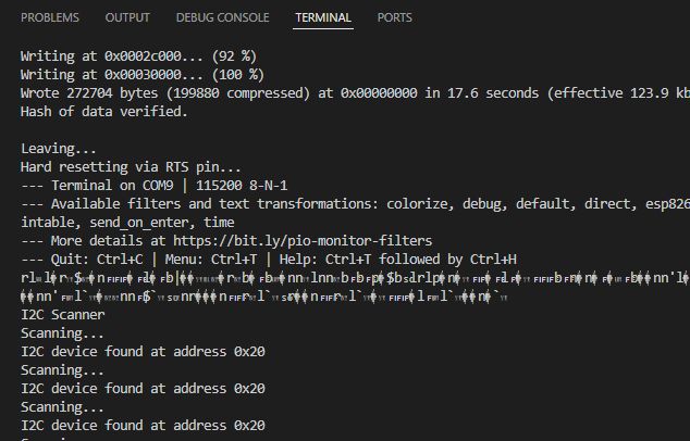
    It works, the layout address is seen:
    Screenshot of a terminal showing I2C scan results. .
    Now the same thing, but for five expanders with different addresses. The connection is trivial:
    Image of eight PCF8574 modules connected in series. .
    Result:
    
    Scanning...
    I2C device found at address 0x20
    I2C device found at address 0x21
    I2C device found at address 0x22
    I2C device found at address 0x24
    I2C device found at address 0x26
    
    .
    All expanders are seen.


    Add the PCF8574 library .
    I've discussed adding a library in PlatformIO before, but basically it's done via Libraries, just click through. Type PCF8574 in the search engine and add preferably the same result as in my screenshot (by Renzo Mischianti):
    Screenshot from PlatformIO showing the PCF8574 library by Renzo Mischianti. .
    The search engine can also show beforehand a library from a 2x16 LCD controlled by the PCF8574, but we care about the PCF8574 control itself. We will run the LCD another time.
    You can see examples of the library when adding it, but I've also put together some simplified demonstrations myself below.


    Blink .
    The library I propose (by Renzo Mischianti) is characterised by a syntax that is deceptively reminiscent of Arduino pins, i.e. we still have here our famous pinMode, digitalWrite and digitalRead, only that not as global functions, but on an object of the PCF8574 class. To instantiate the PCF8574 we use the constructor, which in my example takes the I2C address of the device and the SDA and SCL pins as arguments:
    Code: C / C++
    Log in, to see the code
    .
    Running the PCF, it will tell us if we have connected it correctly and if the address matches:
    Code: C / C++
    Log in, to see the code
    .
    Setting the mode of operation of the pin looks like I mentioned earlier:
    Code: C / C++
    Log in, to see the code
    .
    Similarly setting the value on the output:
    Code: C / C++
    Log in, to see the code
    .
    Full code:
    Code: C / C++
    Log in, to see the code
    .
    Rather nothing to comment on here, the diode simply blinks:


    .
    Obviously the diode connected with a resistor - I gave about 300 ohms to avoid burning the diode.


    Binary countdown .
    Now let's flick all the LEDs. It's probably not necessary, but I was tempted to fire off some simple animation this way. Let's do a binary countdown.
    This is where the first hiccup occurred, because I thought I would expose a byte to the IO pins as I would normally do on a microcontroller, but the function of the PCF8574 class is private....
    
    src\main.cpp: In function 'void loop()':
    src\main.cpp:29:33: error: 'bool PCF8574::digitalWriteAllBytes(byte)' is private within this context
       29 |   pcf8574.digitalWriteAllBytes(x);
    
    .
    Finally, I used the digitalWrite call in the loop... but I leave that to your own interpretation.
    Code: C / C++
    Log in, to see the code
    .
    Works:


    PS: Now I see that defining PCF8574_LOW_MEMORY would maybe help and expose a function that accepts a byte, I leave that for you to try out.

    Button .
    Since there was digitalWrite, we also have digitalRead. What's more, we don't have to connect the pull-up resistor ourselves, because the circuit itself "pulls" the inputs to the logic 1 potential. We can only short them to ground (e.g. with a button) and then we get a low state on it. In this way, we do not need to connect a resistor ourselves.
    Datasheet excerpt describing the reset and initialization of I/Os with an internal current source. .
    So I have connected:
    - a button between GPIO and ground
    - additionally, just for visualisation, an LED on the second GPIO together with a resistor of a few hundred ohms
    Running the pins:
    Code: C / C++
    Log in, to see the code

    Looping, reading the GPIO, writing out to the console (on the UART), and setting the second pin:
    Code: C / C++
    Log in, to see the code
    .
    It works, except that a button released here means state 1, so the LED is on, and a button pressed is state 0 - LED off.


    .


    Button and interrupt .
    What remains to be discussed is the INT pin from the PCF8574. This pin will show a falling edge when something on the input of the PCF8574 changes. This can be used in conjunction with a GPIO interrupt on our NodeMCU to get information that something has happened at the PCF8574, for example someone has pressed a button.
    So we connect INT to, say, GPIO5. Now the interrupt needs to be triggered:
    Code: C / C++
    Log in, to see the code
    .
    The interruptHandler function will call when there is a falling edge (FALLING) on D5:
    Code: C / C++
    Log in, to see the code
    .
    Here, for demonstration purposes, I'm just setting a variable, which I then use to check in the main loop whether the PCF pins need to be read again.
    Code: C / C++
    Log in, to see the code
    .
    The operation is quite similar to the previous example, except that the loop only checks the state of the pins when an interrupt is received.

    More pins can be handled this way - here is an example from the documentation of the library used:
    Code: C / C++
    Log in, to see the code
    .
    This relieves us from having to do a digitalReadAll scan every refresh.

    Can even more outputs/inputs be connected? .
    A version of the chip with different addressing is also available on the market, giving us a total of 128 controlled pins:
    Information about I/O expanders PCF8574 and PCF8574A. .


    Summary .
    A useful and easy to use module. Everything you need is brought out on the goldpins, and also the address selection is quite wide. With 8 pieces you can drive the whole 64 receivers, will anyone need more?
    It's also worth mentioning that the module shown here can do a lot more - there's even an encoder demo in the library used, but I didn't have any on hand to try it out today:
    Spoiler:
    Code: C / C++
    Log in, to see the code
    .
    But even without this, I can conclude that it is a very useful arrangement. What do you think? Have you used the PCF8574 in your projects and if so for what? .

    Cool? Ranking DIY
    Helpful post? Buy me a coffee.
    Do you have a problem with Arduino? Ask question. Visit our forum Arduino.
    About Author
    p.kaczmarek2
    Moderator Smart Home
    Offline 
    p.kaczmarek2 wrote 11989 posts with rating 10016, helped 573 times. Been with us since 2014 year.
  • ADVERTISEMENT
  • #2 21398046
    _ACeK_
    Level 7  
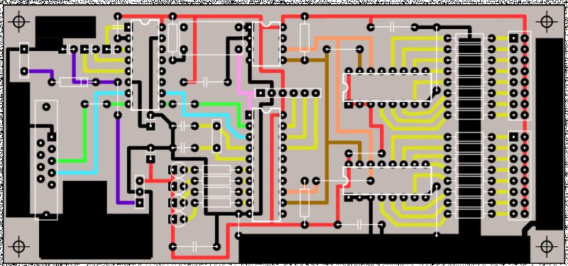
    :) Many years ago tasha developed a very cool ⇨ LXT chip ⇦ I even have a slightly modified board for it ;) .

    Diagram of an LXT electronic circuit with colored paths.
  • ADVERTISEMENT
  • #3 21398168
    p.kaczmarek2
    Moderator Smart Home
    Nice project, a pure classic. I opened the attachment and see files dated 2004:
    List of source files in ZIP file management software. .
    Still that MAX232... I remember running the MAX232 back in my school days and being surprised by this electrolytic capacitor connection, which is deliberately reversed in polarity. At the time I thought that I might still use RS232 in this form, but since then I have only been riding on USB<->UART converters.

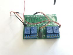
    I myself once did a project based on MCP23017, there are 16 pins there, but the rest is quite similar to PCF:
    Circuit board with relays and wiring. .
    This is the expansion board for:
    Home Assistant/Tasmota HTTP compatible relay controller + housing .
    Helpful post? Buy me a coffee.
  • ADVERTISEMENT
  • #4 21398236
    _ACeK_
    Level 7  
    :) I didn't want to give the exact date because women generally don't like the subject of age being brought up ;)

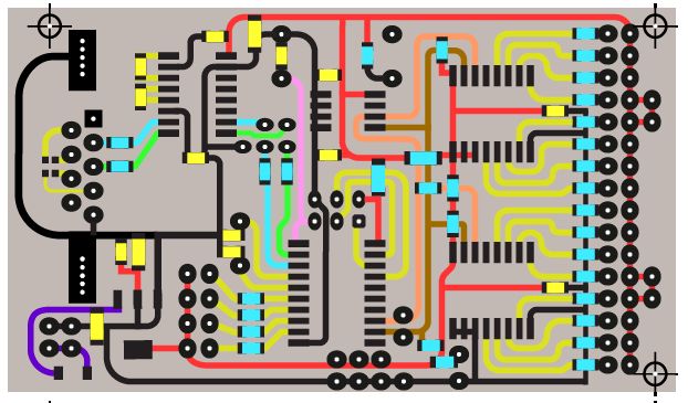
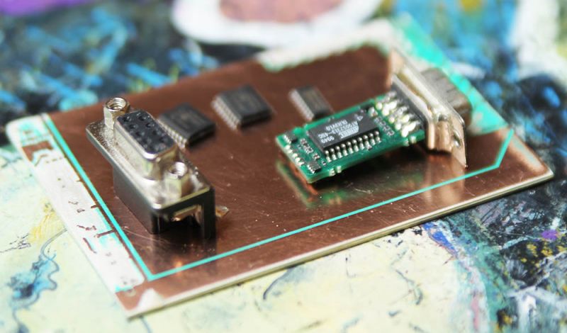
    As it happens, that I'm going to do this layout in a few days :) My version will be SMD . with a choice between MAX3232 and USB ;) .

    Here the almost finished board ⇓

    Image showing a printed circuit board design with colorful traces.
    .
    PCB with electronic components on a colorful background.
    .

    Collected parts and board ⇑ ;) .
  • ADVERTISEMENT
  • #5 21398387
    p.kaczmarek2
    Moderator Smart Home
    What method are you using to make the PCB and how do you ultimately want to organise the LEDs? As far as I can see the original design is a bit lacking in some final effect already, where the LEDs are actually somehow arranged in the title "christmas tree", I don't know, on some mini-tree :D .

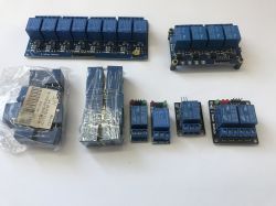
    Although nowadays it's probably simpler to go for WS2812 and the cheapest MCU anyway, maybe I'll do some project where I'll try to drive it with PIC12F. The PCF8574 I would already see more with relays:
    Set of relay modules of various sizes on a white background. .
    Helpful post? Buy me a coffee.
  • #6 21398560
    _ACeK_
    Level 7  
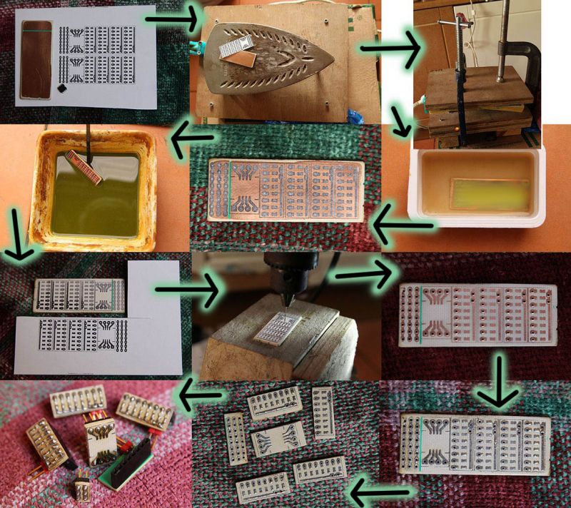
    :) I draw in Illustrator. Then I heat-transfer as shown in the photo ⇓

    The process of producing electronic boards using the iron-on transfer method.
    .
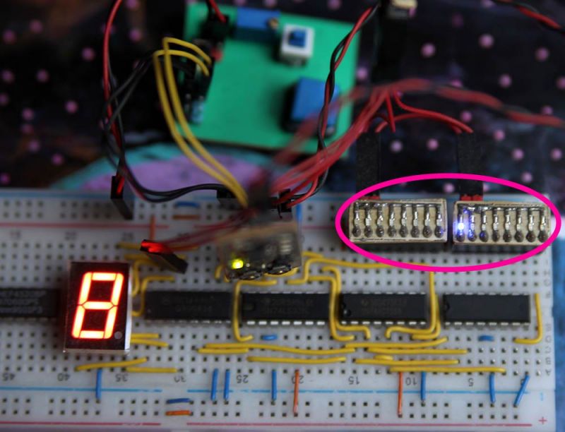
    Breadboard prototype with a 7-segment display and marked I2C pins.
    .

    The layout will be the layout itself for the time being :) The display as in the picture marked with ellipsis ⇑ I have pins I2C , so I can easily view what is happening on the bus ;) .
  • #7 21398585
    kulmar
    Level 32  
    In my opinion, these expanders are form over substance - I usually use sliding registers to expand I/O.
  • #8 21398636
    khoam
    Level 42  
    p.kaczmarek2 wrote:
    There is an INT pin from the PCF8574 to discuss. A falling edge will appear on this pin when something on the PCF8574 input changes.
    .
    There is no way to mask the interrupt for individual PCF8574 pins, and the interrupt is triggered on any state change (both rising and falling edge) on the PCF8574 pins. It is probably better to use the MCP23017 for this purpose.

    Added after 7 [minutes]: .

    kulmar wrote:
    I use sliding registers
    for I/O expansion.
    Typical sliding registers (such as the 74HC595) only handle outputs, while other models (such as the 74HC165) only handle inputs. They cannot be easily switched between input and output modes.
  • #9 21398678
    kulmar
    Level 32  
    And I don't switch - I use both types simultaneously (if I need it). And for typical applications like display control the 75HC595 is not needed. A 74HC164 is enough.
  • #10 21399517
    Karol966
    Level 31  
    khoam wrote:
    Typical shift registers (like 74HC595) only support outputs,
    .
    Well, but you can with an extra pin and together with the use of the cheapest diodes also realise a keyboard with outputs. On the x164 I did such a thing. To operate the keyboard, similar to a matrix keyboard, you sent one state (0/1 depending on the concept) and searched on which position the keyboard output has this, searched state.
    Registers such as the 595 have the advantage that they can also be connected to hardware SPI. For simple applications, such as displaying the status of LEDs or generally controlling unimportant outputs, such sliding registers as the 595/164 are OK, the price is small, so it's worth it. For more restrictive applications, I personally use integrated expanders. The PCF857x is such a dinosaur so I definitely prefer the MCP23017. Unfortunately, more and more often I wonder whether "it made sense", because adding little to the price of the processor I buy one with more IO and the expander becomes unnecessary.

    Only then the board is so poor, not much happens on it :D .
  • #11 21429567
    Mocny Amper
    Level 10  
    The PCF8574 is also quite slow, supposedly it can get a max clock of 100kHz, but I'm using it in a project where I2C goes to 200kHz, and it works flawlessly, but a slight concern I have.
    Well, and the current capacity of the GPIO expander in the high state is lousy, you have to control "zero".
    And it would also be useful to have PWM, which is not available.
  • #12 21432429
    KarolGT
    Level 10  
    Which expander is better, more stable?
    PCF8574 or mcp23017 ?

    or perhaps another, preferably on 16 pins?

    Added after 1 [minute]: .

    Karol966 wrote:
    For more restrictive ones I personally use already integrated expanders. Akurat PCF857x is such a dinosaur so I definitely prefer MCP23017. Unfortunately, more and more often I wonder whether "it made sense", because adding little to the price of the processor I buy one with more IO and the expander becomes unnecessary.
    .
    Can you elaborate? which integrated expanders?
    and which processor are you talking about with more IO instead of an expander?

Topic summary

The discussion revolves around the PCF8574 I/O expander module, which allows for the expansion of input/output ports via the I2C bus. Users share experiences and projects involving the PCF8574, comparing it with other expanders like the MCP23017 and sliding registers such as the 74HC595 and 74HC165. Concerns are raised about the limitations of the PCF8574, including its interrupt handling, speed (max 100kHz), and current capacity. Alternatives for specific applications, such as using integrated microcontrollers with more I/O pins, are also considered. The conversation highlights various project implementations and PCB design methods, emphasizing the versatility and challenges of using I/O expanders in electronic projects.
Summary generated by the language model.
ADVERTISEMENT