FAQ
TL;DR: For Onkyo TX-SR602E no-standby, check D704 (~5.1 V) and remember "POFF is active low." If POFF is asserted, inspect the 13S path and protection parts. [Elektroda, Elektromonterek, post #21551288]
Why it matters: This FAQ helps Onkyo TX-SR602E owners quickly isolate 13S/POFF faults so the receiver powers up.
Quick Facts
- Standby 10VS feeds 13S; the CPU’s 5 V rail is derived from this path. Open circuits here prevent boot. [Elektroda, Elektromonterek, post #21551773]
- CPU VCC observed about 4.94 V at P701 during troubleshooting, yet the unit stayed dead. [Elektroda, _car123, post #21546104]
- IR sensor supply measured ~4.9 V near the STBY LED, confirming standby power presence. [Elektroda, _car123, post #21551142]
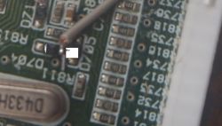
- D704 should be around 5.1 V; if low, POFF can hold the CPU in reset. [Elektroda, Elektromonterek, post #21551288]
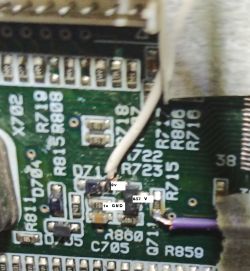
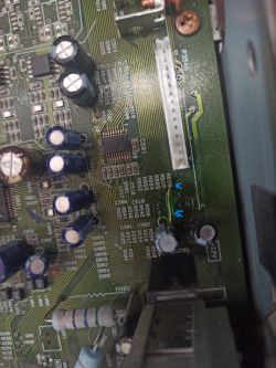
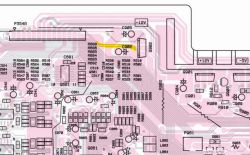
- Root cause found in-thread: corroded trace between P6931B and P354A broke 13S; bridging restored power. [Elektroda, _car123, post #21552312]
How do I fix an Onkyo TX-SR602E that shows no power and no standby LED?
Start at the 13S standby rail. In the documented case, 13S never reached the CPU because a corroded trace between P6931B and P354A was open. Bridge or repair that trace and clean any capacitor leakage. The CPU then exits POFF and the receiver powers up normally. "The 13S pin wasn’t getting any voltage to the CPU, so the power failure detector was active." [Elektroda, _car123, post #21552312]
What does POFF mean on this receiver, and how do I test it?
POFF is the power-fault detect line into the MCU. It is active-low, so a low level blocks startup. Measure POFF and the related protection points: D704 should sit near 5.1 V. If POFF reads low (e.g., ~0.57 V), find why the protection rail is sagging. Edge case: wrong standby transformer or burnt zeners can force POFF low. "POFF is active low." [Elektroda, Elektromonterek, post #21551288]
Where should I measure the standby 13S rail, and what readings flag a fault?
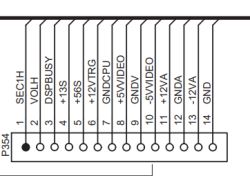
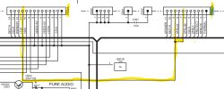
Probe P354 on the 13S net. In a failure example, P354 read ~1.2 V even though the transformer feed at P6931 was ~11 V, and D704 was 0 V. That disparity pointed to an open trace between P6931 and P354, later confirmed as corrosion. Repairing continuity restored proper standby distribution. [Elektroda, _car123, post #21551695]
Is 4.94 V on CPU VCC at P701 enough for the MCU to boot?
Yes, that’s close to nominal, but the MCU still won’t boot if POFF is asserted or the clock is down. The expert guidance here: focus on protection lines, reset, and the oscillator first rather than recapping blindly. "It should be 5 at the proc." [Elektroda, Elektromonterek, post #21547491]
How do I verify the front-panel keys and IR remote input quickly?
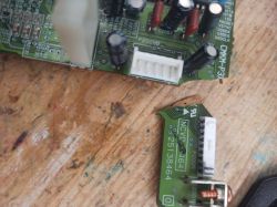
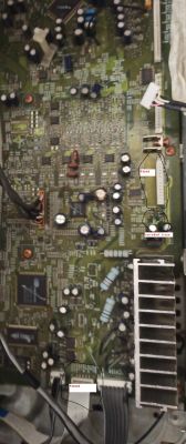
Check LEDSTBY voltage on the front PCB. Then verify the K0–K3 key lines change state when buttons are pressed. Test the IR path by pressing the remote and watching REMIN. If these lines have the expected pull-ups and toggle, the CPU is likely powered but held by protection. Also check Reset, POFF, SYSIN, and SYSOUT. [Elektroda, Elektromonterek, post #21547491]
Can I use an FT232 USB‑UART on P702 to test or reflash the CPU?
Only if P702 exposes the M16C/62P’s UART at TTL levels and the board is placed in serial boot mode. Use a 5 V‑logic USB‑UART and connect TXD/RXD/GND as per the MCU’s serial interface. Enter the device’s boot mode per the manual before attempting flash access. Always confirm the pinout from the service manual first. [Renesas M16C/62P Hardware Manual]
Do I need the video, tuner, or U3 boards connected for standby to work?
No. The 13S/10VS path does not route through those boards on this model. However, ensure that common grounds are properly connected during testing, or measurements may mislead. "It doesn't go through the boards mentioned." [Elektroda, Elektromonterek, post #21551773]
Does leaving the unit plugged in help re-form capacitors?
It can raise rails slightly, but it won’t fix an open 13S path. In this case, leaving the unit on for 45 minutes only lifted CPU VCC to about 4.94 V, with no start-up. That pointed to a distribution or protection issue, not simple cap re-forming. [Elektroda, _car123, post #21546104]
Where do I probe CPU VCC on the TX‑SR602E?
Measure at the firmware writing header P701 on the CPU board. In the reported case, CPU VCC read about 4.7 V there with standby present and the display at ~5.5 V, yet the unit stayed off. That guided attention to POFF and 13S delivery. [Elektroda, _car123, post #21545002]
What should D704 read, and what if it’s at 0 V?
Expect around 5.1 V at D704, matching its zener value. If you see 0 V, the protection rail is not being established. Investigate the 13S source path, series components, and associated zeners. A low here holds POFF active and prevents the CPU from starting. [Elektroda, Elektromonterek, post #21551288]
Quick 3‑step: How do I trace the 13S feed from transformer to CPU?
- Measure the standby transformer output at P6931; confirm presence.
- Check P354 (13S) for proper voltage; compare with P6931.
- If P6931 has voltage but P354 is low, inspect and repair the trace between P6931B and P354A, cleaning any leaked electrolyte. [Elektroda, _car123, post #21552312]
What edge cases can still block startup after 13S is restored?
A failed resonator can stop the CPU clock. Burnt zeners on the protection network can clamp rails and assert POFF. In rare cases, an incorrect standby transformer was installed, overdriving the protection circuit. These conditions keep POFF low and the unit off. Verify the clock and protection components before suspecting firmware. [Elektroda, Elektromonterek, post #21551288]


