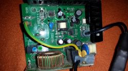
Electrolux Beam BM285EA hoover
Symptoms: In the early days the hoover would sometimes not switch off. It would run for about 10-20 seconds after switching the control to OFF. Another symptom was the control going into a 'sleep' state. The LED next to the on/off switch went out and the unit was completely inactive. Switching off the mains and replacing the cable with another helped for a few days. After this time, the fault returned. It turned out that it was not the fault of the cable, but of the module, which only needed to be restarted and then continued to work for a few days - hours - variously, until it stopped working altogether. At the same time, the restart caused the readiness LED to light up for a few seconds.
Measurements:
On the power supply board, inverter output voltage 5 V stable (D6).
Voltage on Zener diode D8 - pins 5 V - 18 V at inverter operating frequency. At the same time, the same oscillogram on the output of the divider (R20; R19).
 .
.
The output of the divider goes to the input of the comparator (LM339) on the processor board.
Suspected capacitance fault in R14, C7 circuit.
A 470 nF capacitance was temporarily used.
The effect was to straighten the voltage to about 4 volts and start the circuit.
Unfortunately, after installation in the hoover, this one worked for a few minutes. After this time, the diode went out again, and the restart again ended with it glowing for about a second.
Measurements:
I looked at the oscillogram behind the 4N35 optocoupler.
Rectangular waveform with grid frequency in the range max 5 V, min 3.8 V.
Suspected optocoupler fault.
During replacement I noticed a broken diode D13, no markings.
It is part of the report voltage of the power supply based on transistor Q1. Calculations indicated that it should have a value of approximately 1.4 V. In the absence of such a diode, a diode glowing in the conduction direction was used and the optocoupler was replaced.
After replacing the aforementioned components, the oscillogram took a value of max 5 V, min 0.2 V and the circuit returned to normal operation.
Suggestions:
Check the waveform after the optocoupler and at the output of the R20/R19 divider.
They should be as in the posted description.
Good luck. (I am attaching a photo by one of my colleagues)
Symptoms: In the early days the hoover would sometimes not switch off. It would run for about 10-20 seconds after switching the control to OFF. Another symptom was the control going into a 'sleep' state. The LED next to the on/off switch went out and the unit was completely inactive. Switching off the mains and replacing the cable with another helped for a few days. After this time, the fault returned. It turned out that it was not the fault of the cable, but of the module, which only needed to be restarted and then continued to work for a few days - hours - variously, until it stopped working altogether. At the same time, the restart caused the readiness LED to light up for a few seconds.
Measurements:
On the power supply board, inverter output voltage 5 V stable (D6).
Voltage on Zener diode D8 - pins 5 V - 18 V at inverter operating frequency. At the same time, the same oscillogram on the output of the divider (R20; R19).
 .
.
The output of the divider goes to the input of the comparator (LM339) on the processor board.
Suspected capacitance fault in R14, C7 circuit.
A 470 nF capacitance was temporarily used.
The effect was to straighten the voltage to about 4 volts and start the circuit.
Unfortunately, after installation in the hoover, this one worked for a few minutes. After this time, the diode went out again, and the restart again ended with it glowing for about a second.
Measurements:
I looked at the oscillogram behind the 4N35 optocoupler.
Rectangular waveform with grid frequency in the range max 5 V, min 3.8 V.
Suspected optocoupler fault.
During replacement I noticed a broken diode D13, no markings.
It is part of the report voltage of the power supply based on transistor Q1. Calculations indicated that it should have a value of approximately 1.4 V. In the absence of such a diode, a diode glowing in the conduction direction was used and the optocoupler was replaced.
After replacing the aforementioned components, the oscillogram took a value of max 5 V, min 0.2 V and the circuit returned to normal operation.
Suggestions:
Check the waveform after the optocoupler and at the output of the R20/R19 divider.
They should be as in the posted description.
Good luck. (I am attaching a photo by one of my colleagues)


