logo elektroda
logo elektroda
X
logo elektroda

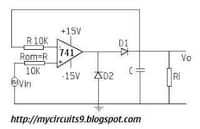
Peak detector circuit with 10k resistors, 1uF/10uF cap, IN914 diode, 15V op-amp not working

42 9
ADVERTISEMENT
  • ADVERTISEMENT
  • #2 21665835
    Eugene Lisovy
    Anonymous  
  • ADVERTISEMENT
  • #3 21665836
    David Adams
    Anonymous  
  • #4 21665837
    Earl Albin
    Anonymous  
  • #5 21665838
    Steve Lawson
    Anonymous  
  • ADVERTISEMENT
  • #6 21665839
    Earl Albin
    Anonymous  
  • ADVERTISEMENT
  • #7 21665840
    Steve Lawson
    Anonymous  
  • #8 21665841
    Earl Albin
    Anonymous  
  • #9 21665842
    Safwan RAJAB
    Anonymous  
  • #10 21665843
    PeterTraneus Anderson
    Anonymous  

Topic summary

A peak detector circuit using 10k resistors, 1µF or 10µF capacitors, an IN914 diode, and a 15V powered op-amp (LM741) was not producing the expected output. Key issues discussed include the importance of input signal frequency and amplitude, as the peak detector functions for AC signals and may fail at high frequencies (e.g., 1MHz) due to the op-amp's internal resistance and RC time constant with the output capacitor. The LM741 op-amp's input voltage range and output swing limitations were highlighted, with a reminder to consult the datasheet to avoid input voltages exceeding supply rails, which can cause latch-up in some ICs (though LM741 claims no latch-up). A suggested correction involves adding a 100nF capacitor at the op-amp output to stabilize the circuit. Another modification recommended moving the diode anode from ground to the junction of the op-amp's inverting input and the 10k resistor. The circuit was noted to behave like a half-wave rectifier, charging the output capacitor to the peak input voltage if conditions are met. Proper grounding and signal tracing with an oscilloscope or AC voltmeter were advised to diagnose the issue further.
Summary generated by the language model.
ADVERTISEMENT