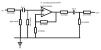
You tried moving your hand near the circuitry. Excellent, this is a good diagnostic for RF pickup or oscillation problems. Try grounding the input to the circuit: Does the noise go away? Listen to the noise: Can you hear music or speech in the noise? If so, you have radio-station pickup. What are the strong local stations in your area? AM or FM or other?
As David suggests, add a capacitor across one of the 100K resistors. You could add a 100-ohm resistor in series with the 47 uF capacitor between the 100K resistors, and add shunt capacitors across both 100K resistors. The shunt capacitors should have reactance of 100 ohms at 30 kHz, assuming your audio signal source is low-impedance, and should have zero lead length to minimize series inductance. Series inductance is why David recommends parallel capacitors for supply bypassing.
For the unused opamp, ground the plus input, and connect the minus input through a 10K ohm resistor to the output.If not using a PCB, build the circuit using dead-bug ugly construction, as popularized by radio amateurs for building VHF and UHF receivers. Start with an unetched copper-clad board with the copper side up. The copper is your ground plane. Lay the NE5532 on its back, so its leads are sticking up (hence dead-bug) on the board. Mount bypass capacitors with zero lead length between each power pin and the ground plane. Use leaded capacitors, as SMT capacitors fracture easily. Keep all parts and leads close to the ground plane. Use 10 pF capacitors to make tie points.I recall teaching these solutions to this problem to a group of experimental physicists when I was an undergraduate in college in 1969.


