Elektroda.com
Elektroda.com
X
This content has been translated flag-pl » flag-en View the original version here.
  • Power amplifier on NE5532 - ty.ytka

    It may seem ridiculous, but you can build an interesting power amplifier from ordinary operational amplifiers (with the right amount of them). :)

    From this "miracle" I achieve 2×14 W on a load of 8 ohms. Maybe this value is not shocking, but considering what we get it from, it's probably not a little bit.

    First things first.
    This project was created only as an experiment, made out of curiosity.
    The source of inspiration for this project was an article by Douglas Self in the Elektor magazine (issues 10 and 11 of 2010). Whereas the design of my headphone amplifier ( link ) served as a fitting for this very crazy project.

    However, my project is not an exact copy of the mentioned article. I simplified it a bit in my experiment. I resigned from balanced inputs and the possibility of connecting both channels into a bridge. I made the security system on uPC1237, and the stabilizers on LM338.

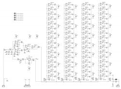
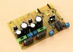
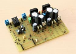
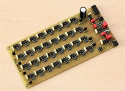
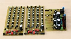
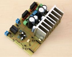
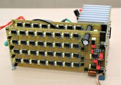
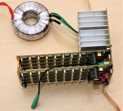
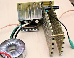
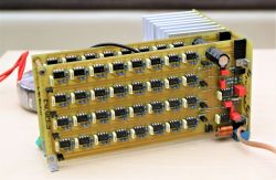
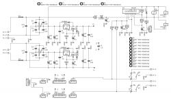
    I assembled the whole amplifier on three boards. One containing stabilized power supplies, supplying +/-18 V, and a loudspeaker protection system. The other two contain amplifiers for each channel. Each channel contains 4 operational amplifiers in the voltage amplifier part, 64 operational amplifiers connected in parallel working as an output buffer and one op-amp operating in the DC-servo system.

    Tile schemes:
    Power amplifier on NE5532 - ty.ytka Power amplifier on NE5532 - ty.ytka

    A few photos of the assembled layout:
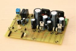
    Power amplifier on NE5532 - ty.ytka Power amplifier on NE5532 - ty.ytka Power amplifier on NE5532 - ty.ytka Power amplifier on NE5532 - ty.ytka Power amplifier on NE5532 - ty.ytka Power amplifier on NE5532 - ty.ytka Power amplifier on NE5532 - ty.ytka Power amplifier on NE5532 - ty.ytka Power amplifier on NE5532 - ty.ytka

    Now maybe a few words about the impressions of the final effects.
    Overall, I perceive the amplifier very positively from the listening point of view. The presented sound is quite detailed, clean without coloration. I was surprised by the quality of the bass, but in my opinion it is due to the quality of the power supply (stabilizers).

    For now, I do not plan to use this project for a specific purpose, but I also do not rule it out in the future. However, it is quite interesting in terms of sound.
    However, if someone wanted to use something like this for a specific purpose, remember to ensure proper cooling. Unfortunately, the stabilizers have to dissipate quite a lot of heat, and even the operational amplifiers themselves heat up to about 45-50 degrees Celsius during such operation.

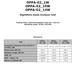
    Something about parameters.
    Output power with simultaneous control of both channels - 2×14W on 8 ohms .
    Other parameters are presented in the table below. Values for three different output powers 1W, 10W and 14W .
    Power amplifier on NE5532 - ty.ytka

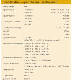
    The author of the article mentioned at the beginning achieved slightly different parameters in his experiment:
    Power amplifier on NE5532 - ty.ytka

    The differences in the obtained parameters could have been influenced by the simplification of my system and the fact that I used the cheapest version of NE5532, because " P ".

    Cool? Ranking DIY
    About Author
    tytka
    Level 21  
    Offline 
    tytka wrote 607 posts with rating 1559, helped 7 times. Live in city Pabianice. Been with us since 2006 year.
  • #2
    marweg1967
    Level 12  
    tytka wrote:
    This project was created only as an experiment, made out of curiosity.
    The source of inspiration for this project was Douglas Self's article published in Elektor magazine (no. 10 and 11-2010).


    I read that article some time ago (although not in Elektor) and I was very interested in it. So much so that I also decided to implement this seemingly crazy project someday. Unfortunately, the word "someday" is crucial here, because I suffer from a chronic lack of time, and I only "grow" electronics as a hobby. But now my colleague cheered me on and I will have to change "someday" to "soon" :) Especially that the final effect (listening) is, according to my colleague, more than encouraging. By the way, I consider Douglas Self's publications excellent and it is a pity that none of them were published in Polish.

    Where did my colleague buy the working uPC1237?

    Regards!
  • #3
    rb401
    Level 38  
    tytka wrote:
    This project was created only as an experiment, made out of curiosity.
    The source of inspiration for this project was Douglas Self's article published in Elektor magazine (no. 10 and 11-2010). However, the design of my headphone amplifier (Link) served as a fitting for this crazy project.


    The concept seems older than 2010 to me.
    Your performance is very nice. I also like that you managed on a single-sided PCB.

    Such a curiosity. Recently, on Aliexpress, I also came across several such reactivations of this old idea. Actually, the power amplifier boards themselves.
    Unfortunately, I couldn't get to the details, diagram, etc. it's hard to refer to these offers.
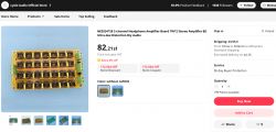
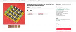
    The interesting thing about the Chinese is that they offer some versions without amplifier cubes. The plates are fitted with precision sockets. And in the descriptions for complete performances, they boast that the picks are second-hand, i.e. stimulants. You can also see that they are reluctant to put on cheap ones from their market: brand new, 100% original, genuine.

    First from the shore, examples:
    Power amplifier on NE5532 - ty.ytka
    https://www.aliexpress.com/item/1005004652826097.html

    Power amplifier on NE5532 - ty.ytka
    https://www.aliexpress.com/item/1005001273625129.html
  • #4
    mkpl
    Level 37  
    Overall nice but for the fan and for fun.
    What did you measure with? Do you have a card reference measurement? Because you don't know where the measurement limits are. The second thing, do you have a differential measurement on the load or asymmetrically? The asymmetric measurement generates a ground loop from the card output through the amplifier, the ground cable to the load, and the card input ground. For me, changing the configuration improved the tip noise signal from 102dB of dynamics to 110dB.
    Similar parameters are achieved by simple power amplifiers based on transistors :) but they're not that impressive.
  • #5
    tytka
    Level 21  
    I also found similar modules on Aliexpress.
    Only they break everything into mini-blocks. Those boards that colleague rb401 pointed out are the output buffers themselves.
    They even offer such little things:

    Power amplifier on NE5532 - ty.ytka
    https://pl.aliexpress.com/item/1005003424837886.html?gatewayAdapt=glo2pol

    And this is an example of a voltage amplifier:
    Power amplifier on NE5532 - ty.ytka
    https://pl.aliexpress.com/item/1005004651433459.html?gatewayAdapt=glo2pol

    I bought working uPC1237 in China. Now only they produce these systems. But the fact is that shopping with them involves some risk.

    The measurement results, I know, are not impressive and I have already made transistor amplifiers that achieved better results in tests. But as I mentioned, I did not chase test results here (cheapest NE5532, etc.). It was more about listening to it.

    The measurement was made asymmetrically. I will post the reference measurement of the card in the evening.
  • #6
    Urgon
    Level 38  
    AVE...

    This is a very well made design, and an interesting concept, although usually parallel connection of operational amplifiers is practiced in order to reduce noise in ultra-sensitive measuring amplifiers. Parameters are great too. I would say that it is an audiophile construction, but I do not want to offend you. ;)
  • #7
    katakrowa
    Level 22  
    Considering that for 5 USD we can buy 100 pieces of NE5532 in SMD, the project makes quite a lot of sense.
  • #8
    Urgon
    Level 38  
    AVE...

    The only question is, are these cheap NE5532 originals or Chinese clones? If they are clones, do they therefore keep their parameters?
  • #9
    gulson
    System Administrator
    Very interesting design, that's what DIY is for!
    Write to me in a parcel locker and I will be happy to send you a gift.
  • #10
    tytka
    Level 21  
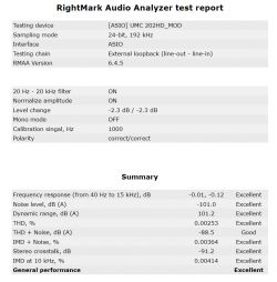
    Here is the promised reference measurement of the card used for the measurements:

    Power amplifier on NE5532 - ty.ytka

    And as for the price with the NE5532 used.
    As I mentioned, I used the NE5532P from TI. I bought them at TME, with this amount (without any additional discounts) they came out below 1.9 gross per item.
  • #11
    pikarel
    Level 36  
    This is real DIY, in an exemplary execution; that's what the DIY department is for.
    Now we are waiting for posts that will expose "non-compliance of the device made with the standards", buddy @tytka :)
  • #12
    austriackimalarz
    Level 26  
    pikarel wrote:
    Now we are waiting for posts that will expose "non-compliance of the device made with the standards", buddy @tytka

    Who was calling me? ;)
    I really like this experiment. Generally, connecting several amplifiers in parallel eliminates noise, but ... without exaggeration ;P
    Maybe it's worth using amplifiers in SOT23-5 enclosures for a similar experiment? In addition, a 4-layer PCB would allow thousands of amplifiers to be mounted on a small surface.
    edit:
    Such an AS321KTR-G1, tiny, costs pennies, +-12V power supply.
  • #13
    lechoo
    Level 39  
    tytka wrote:
    Here is the promised reference measurement of the card used for the measurements:

    Power amplifier on NE5532 - ty.ytka

    Can you reveal what you modified in UMC202HD to get such good parameters?
  • #14
    rb401
    Level 38  
    austriackimalarz wrote:
    Such an AS321KTR-G1, tiny, costs pennies, +-12V power supply.


    I strongly warn against using these cubes and others from the LM321, 358, 324 group in this construction.
    It's just that in these amplifiers, in applications where the output current changes direction, there is a moment when the output voltage "dies". And here in such a terminal there are ideal conditions for this phenomenon to occur and spoil all the advantages of this construction.
    More on this issue in this thread:
    https://www.elektroda.pl/rtvforum/topic3643822.html
  • #15
    tytka
    Level 21  
    @lechoo I limited the input path of this card to a minimum, because as it turns out, the factory Midas input amplifiers are a total flop and the reason for the imperfection of this card. I described my modification here: https://www.elektroda.pl/rtvforum/topic3655998.html
    Now, for security, I put some protection on the input. And this is after I recently burned the input AD8694.
  • #16
    marweg1967
    Level 12  
    tytka wrote:
    @lechoo I limited the input path of this card to a minimum, because as it turns out, the factory Midas input amplifiers are a total flop and the reason for the imperfection of this card. I described my modification here: https://www.elektroda.pl/rtvforum/topic3655998.html
    Now, for security, I put some protection on the input. And this is after I recently burned the input AD8694.


    Will your colleague reveal details about this security? Input diodes? Because this Behringer really hums badly and I'm getting ready to etch the board to use the workaround described by a colleague (I already have parts). So I would add that security right away. You have to learn from your mistakes, preferably someone else's ;) By the way, I bought this Behringer instead of Focusrite, because the price "captivated" me. Well, the proverb that the cunning man loses twice has come true :(

    Regards!
  • #17
    kamil.b
    Level 12  
    It is conceptually similar to this project:


    Headphone amplifier based on NE5532

    Quite a neat design (both the author's and Phil's from the movie)
  • #18
    austriackimalarz
    Level 26  
    rb401 wrote:
    I strongly warn against using these cubes and others from the LM321, 358, 324 group in this construction.
    It's just that in these amplifiers, in applications where the output current changes direction, there is a moment when the output voltage "dies". And here in such a terminal there are ideal conditions for this phenomenon to occur and spoil all the advantages of this construction.
    More on this issue in this thread:
    https://www.elektroda.pl/rtvforum/topic3643822.html

    Thanks for the information, I didn't know about that.
    I'm thinking... Let's give 4 sets of amplifiers powered from +-22V, let's connect them into 2 separate bridges. This would give 44Vpeak, which at 8 ohms will allow 100W of power draw from the amps.
    Now I have to find an operational amplifier cheap enough to meet the assumptions and with enough parameters to work in audio, so that I can afford to buy a few thousand pieces and create such a monster.
    I already have a transformer for it :D Also the GU-81M amplifier will wait, first something.
    I assume the simplest cooling - I will throw the whole thing into a sealed housing and flood it with a transformer, and possibly some computer cooler.

    EDIT:
    LM2904AQTH-13 in TSSOP-8 package.
  • #19
    rb401
    Level 38  
    austriackimalarz wrote:
    EDIT:
    LM2904AQTH-13 in TSSOP-8 package.


    This cube is basically the same as the LM358 and has the same characteristic of these specific distortions as this whole family.
    So it is definitely not suitable for this construction.
  • #20
    austriackimalarz
    Level 26  
    This generally looks like a feature of BJT-based amplifiers. Versions based on JFET transistors do not have such problems.
  • #21
    rb401
    Level 38  
    austriackimalarz wrote:
    This generally looks like a feature of BJT-based amplifiers. Versions based on JFET transistors do not have such problems.


    It's not about that at all. It's just that in the LM358 and types directly derived from this design, the final stage uses push-pull without quiescent current. And a situation arises where a certain time is needed to switch between the "upper" and "lower" transistors, which can be seen on the waveforms. In return, you gain low power consumption by these amplifiers. So generally, these are not cubes for push-pull work, but rather for work in class A, i.e. with asymmetrical load. But this is a matter of the adopted solution in this construction, not the manufacturing technology.
  • #22
    austriackimalarz
    Level 26  
    Really. So I made the wrong conclusions. However, the LMV358, the low-voltage version of the circuit without the "V" which is free of this disadvantage, has no quiescent current per se, but is largely made of junction transistors.
    Well, I'm still looking, but it's hard.
  • #23
    tytka
    Level 21  
    marweg1967 wrote:
    Will your colleague reveal details about this security?

    I will, but give me some time. There's one option already, but I'm thinking of another. I want to etch the tiles now and check it out. Then, after the tests, I will propose what and how.
  • #24
    marweg1967
    Level 12  
    tytka wrote:
    marweg1967 wrote:
    Will your colleague reveal details about this security?

    I will, but give me some time. There's one option already, but I'm thinking of another. I want to etch the tiles now and check it out. Then, after the tests, I will propose what and how.

    In that case, I will wait with my plate for the results of your tests. Many thanks and best regards!
  • #25
    yogi009
    Level 43  
    An interesting approach to the construction of the power amplifier :-) The parameters will be very good, because the cube itself (despite the low price) is definitely musical. A big plus from me.
  • #26
    nyquist
    Level 26  
    Interesting design. I suspect that with the right power supply, the system can sound really good. A plus from me too.
    ps. Who will be tempted to build a similar power amplifier on the OPA627? ;-)
  • #27
    marweg1967
    Level 12  
    nyquist wrote:
    Who will be tempted to build a similar power amplifier on the OPA627?


    One channel for about 4 k PLN? Well, Lord, it's almost high-end. Something just in time for another block to the resurrected Unitra. ;)
    By the way, I wonder how it would look during blind listening compared to the work of the author of the topic.
  • #28
    tytka
    Level 21  
    As already OPA627, I suggest in TO-99 housings :) with heat sinks on them, which would make sense from a cooling point of view.
    Unfortunately, then the cost of such an undertaking would even exceed the price of the new WSH-805 from Unitra.
  • #29
    Urgon
    Level 38  
    AVE...

    You can use the SOIC version and do it on a double sided board. All circuits on one side, other components in the SMD variant on the other. Then, grease the amplifiers with thermal paste and screw the entire plate to the heatsink ...
  • #30
    tytka
    Level 21  
    If a commercial version were to be created, such a solution should be seriously considered.