Dear EE_Newbie,
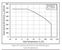
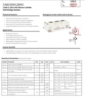
No, the way a 3-phase bridge works is that you turn on just two FETs in two different legs at a time, one on the high side and one on the low side. As your diagram shows, FET 1 and 4 are turned on. Current then flows down through FET 1, out phase U, through the load, into phase V and down through FET 4. The current is not predetermined. Rather, the bus voltage is predetermined. Thus the amount of current that flows is determined by the bus voltage and the load characteristics. For example, if the bus voltage is 300 V and the load is 10 ohms, 30 A will flow. If the load is 1 ohm, 300 A will flow. As Richard points out though, the FETs must be rated for more than 300 A and be properly heat sunk to avoid damaging them.
Note that at the instant in time when FETs 1 and 4 are on, FETs 5 and 6 are off, thus no current flows in the third leg. Also, the load is often inductive, like when driving a motor, so any current will continue to flow even when the switches open back up. In that case, referring to your diagram, the current will continue to flow out of U and into V, but since FETs 1 and 4 are now open, it will find its way back up into the bus through the body diodes of FETs 2 and 3 (yes, against the bus voltage!) until another pair of FETs turns on or the energy of the inductance dissipates.
There is a lot more to it than what I have described (see the reference that Richard mentioned). Hopefully we are helping to get you better oriented to 3-phase bridge operation though.
Enjoy! -JD


