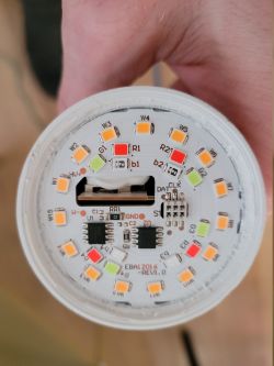
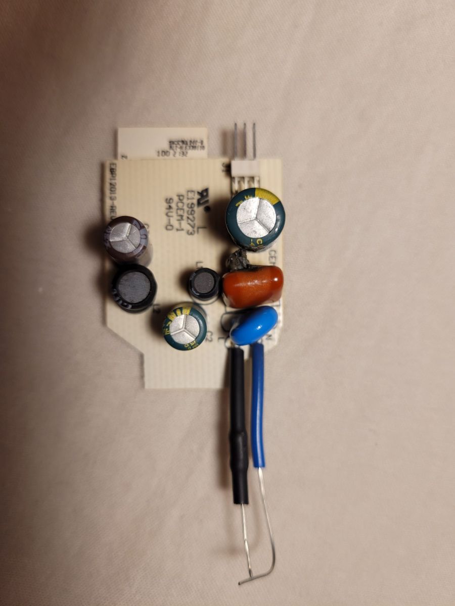
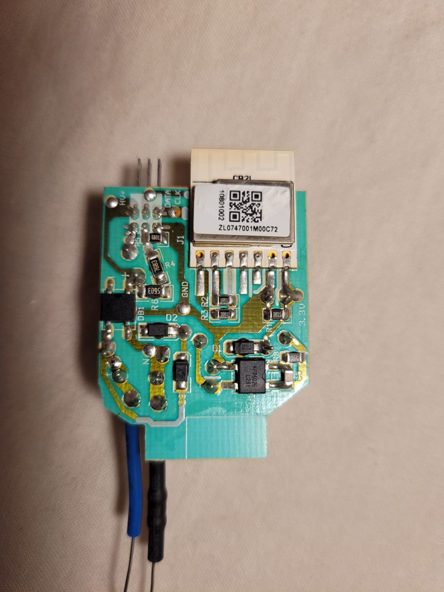
230V LED Nous smart WiFi Bulb P3 repair help needed.
Bulb doesn't work. Multimeter shows:
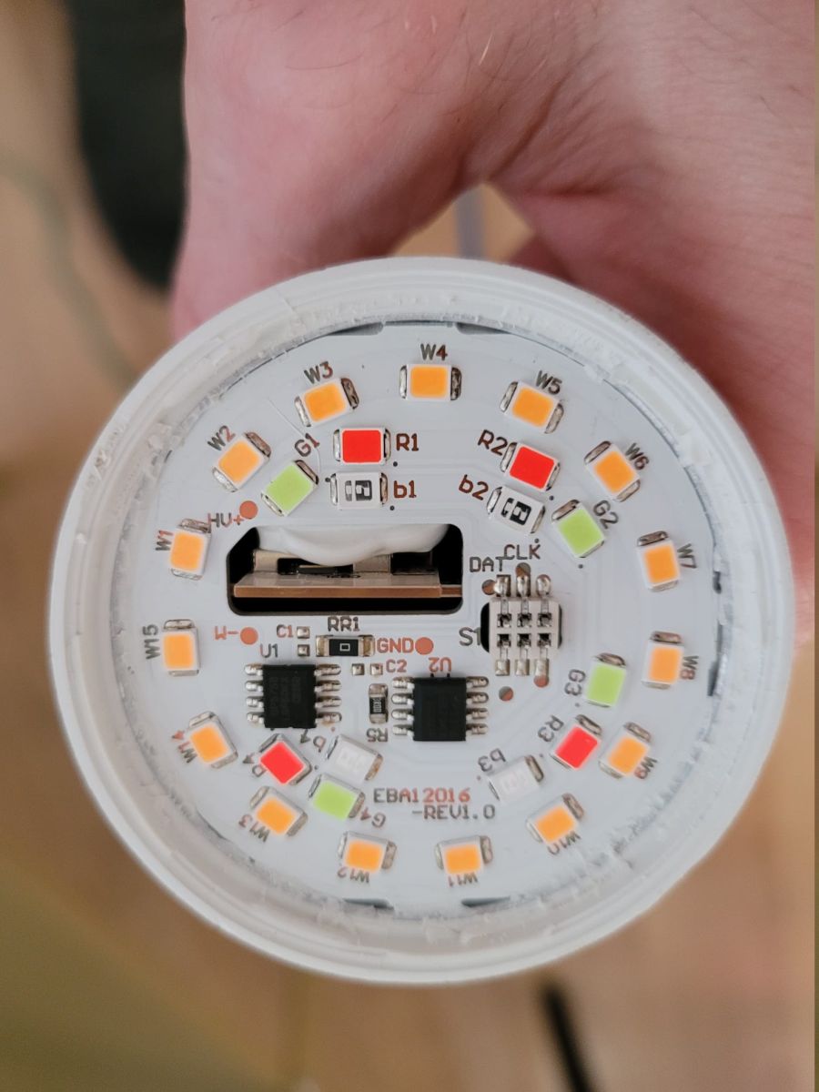
GND - W-: 0.15V
GND - HW+: 0.12V
HW+ - HW-: 0.14V
I tried shortening all LEDs one by one - didn't help. The LEDs also doesn't light when I test each with continuity/diode tester (with mains power removed). How to proceed?
AI: Does the bulb show any signs of life at all (WiFi pairing/AP visible, brief flash, any LEDs glowing), and is there any visible damage on the PCB/components such as burnt parts, cracked capacitor, or blown fuse resistor? No signs of life. No visible damage.
AI: Can you share where exactly those voltages were measured, and what voltage you have at the mains input and on the main DC bus after the bridge rectifier/filter capacitor when powered from 230V? The labels are on the attached picture.
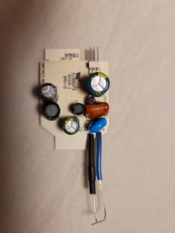
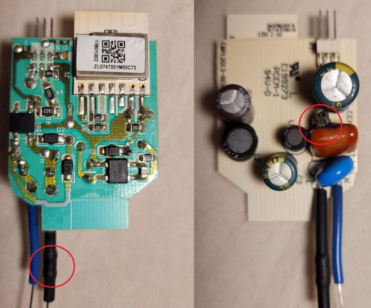
Ok, I see CEM1-1 has burned.
When you start playing with LEDs get a LED tester, preferably one that is yellow 0-320V Link Three times check what you are buying and what you are paying for.... If they are normal pink-coloured diodes (2-PIN) you will check them with the above mentioned tester, and if they are 4-PIN programmable diodes you will not check them with the above mentioned tester....
In your case, in order to test electronic circuits besides LEDs, take a more detailed picture of 8-PIN ICs (U1 and U2) - look for their names in datasheets and you will find out what and where to measure, because the datasheets give numbers of legs (pins) and required supply voltages and sometimes whole schematics of typical applications...
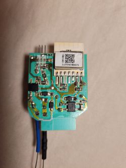
The shown part of this light source is not a whole because the power supply and control part is missing - probably the remote control and that is probably where your problem lies, although not always...
When you start playing with LEDs get a LED tester, preferably one yellow 0-320V
A tester for over PLN120 to repair ONE LED bulb for a dozen or so? (I know more expensive, but certainly not as much as a tester).
elktrod wrote:
if these are 4-PIN programmable diodes
From the photo you can see what kind of diodes these are and they are definitely not any programmable ones but the most ordinary ones in several colours (as indicated by the flood of diodes)
martinspukitismail wrote:
The bulb does not work.
At all? If not a single LED is illuminated then you need to focus on the mains power supply circuit - there will probably be a bridge, an electrolytic capacitor for the high voltage and, depending on the design, either the transistor key of the switching power supply or something to step down the voltage to the required value (inherently a few tens of V max) to supply the LED array. The power supply I am writing about is located on the perpendicular to the plate shown in the photo inside the LED bulb housing.
And now the most important thing - If the author has no experience with mains voltage powered circuits a better option would be to buy a second LED bulb.... There are really life-threatening voltages out there, and for the power supply measurements to be taken the bulb has to be switched on....
P.S. I understand that the Author has a universal meter and knows how to use it?
ADVERTISEMENT
Measure burnt capacitor size and replace electrolytics
@martinspukitismail, sorry I didn't look at your original message yesterday because two of your images didn't show up in my (Polish) forum. It was only today when I clicked on the "Show original message" option that these pictures of yours appeared
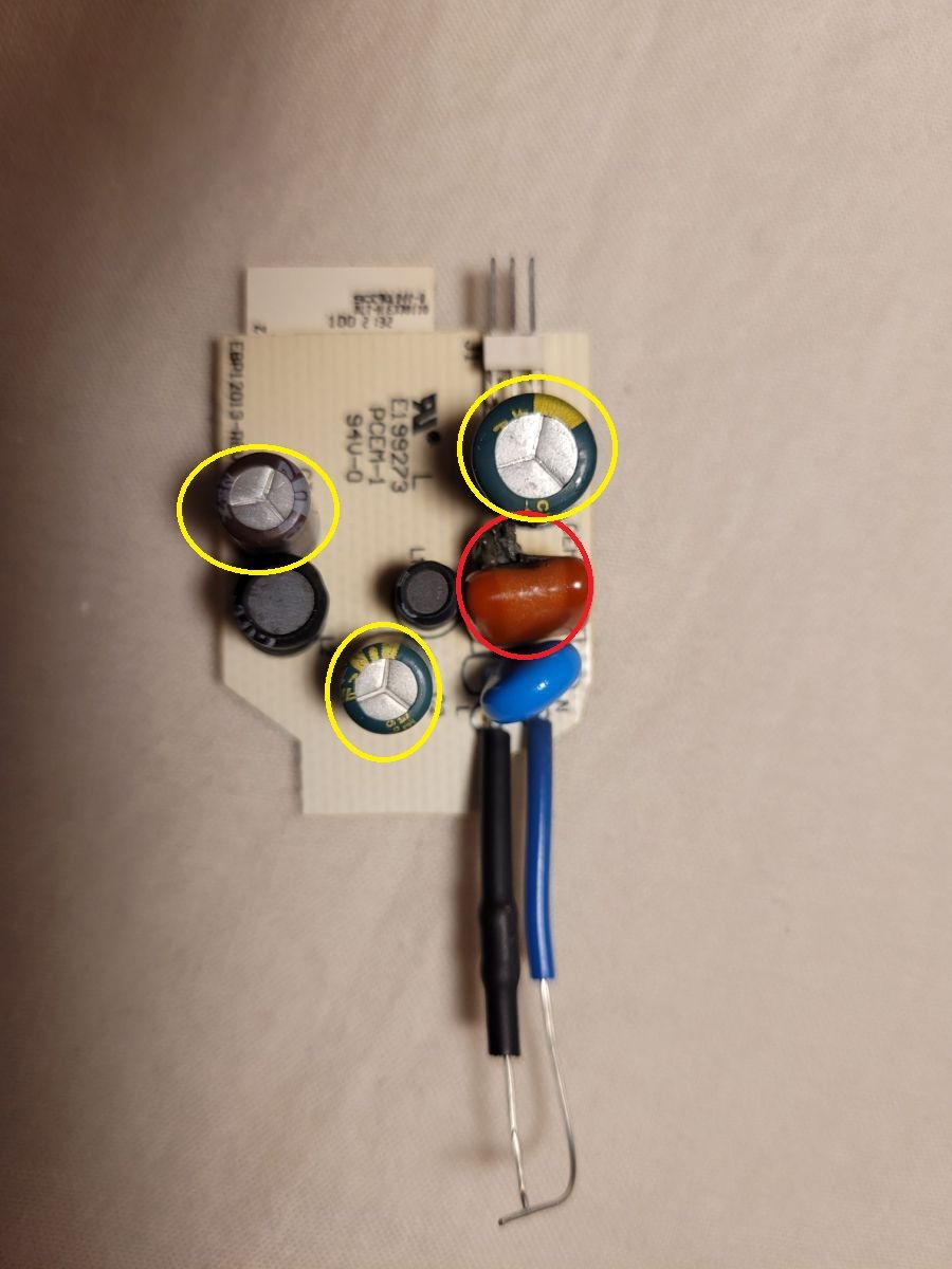
and on one of them according to me (I may be wrong) you can see a burnt capacitor (I marked it in red on the above mentioned picture), try to see if there are any inscriptions on the unburnt side? If there are no inscriptions then measure the dimensions of this capacitor with my caliper: length, width and thickness. By eye, it should be rated at about 864J, which means it could be about 860 nF, but it would be better to find this out in the other way described above, or someone else will tell you if they have one in their collection... Also replace the electrolytic capacitors marked in yellow. And for testing their efficiency after discharge, of course I recommend another tester this time: Link Take a closer look at the circuit to see if any resistors or other components are soldered in parallel to the suspected burnt capacitor then check them....
Also measure the resistance of the resistor in the black shrink sleeve and if there is no resistance then carefully remove the sleeve to read what is written on it....
Everyone once started the adventure with electronics and if it is not a one-time adventure, I in good conscience recommend both of the above-mentioned testers, which will make it easier for you to diagnose in the future, as well as whether it is necessary to replace some of the components I write about, e.g. electrolytic capacitors marked in yellow?
I can see from your other topic https://www.elektroda.pl/rtvforum/topic4168746.html that this is not your first adventure with electronics and by the bulge of the capacitors you can recognise their defect, but this bulge is not always visible, so in good conscience I recommend the above mentioned testers even if others disagree and criticise me, I have my opinion....
PS. I know that sometimes it is difficult or the equipment does not allow you to, but try to take pictures with a better sharpness, because not everyone has a falcon eye, I do not have it anymore due to sitting in front of a monitor...
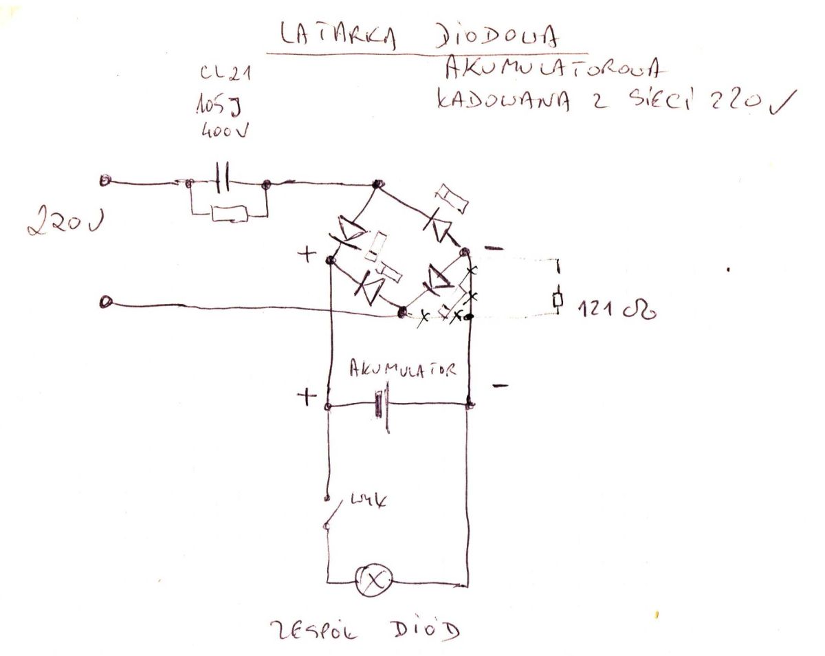
Sometimes it is helpful to try to draw a diagram of some device you want to repair, e.g.: https://www.elektroda.pl/rtvforum/topic4091076.html Below I show you a schematic of a rechargeable LED torch that I once drew to show you a typical way of getting a lower voltage from 230V AC mains to get a DC voltage of about 4-5V using a capacitor and a resistor connected in parallel and a bridge rectifier (Graetz circuit) and you should already know what voltage to expect and where to make and what kind of measurements in AC or DC mode... it will be much easier if you try to draw the power supply circuit for your light source...
For the correct operation of any circuit you need to establish the efficiency of the above mentioned components and if they do not correspond to the original designed or applied values or are burnt out then replace them....
I would like to point out, however, that the values of spare parts for bad ones you have to determine precisely because the communication module is also powered from this circuit, so the original conditions of its power supply must be created and these depend on the mentioned elements and their values and unless it has undergone failure, by the way, this will be your next successful repair this time of this light source when the cause of the burnt-out of the aforementioned capacitor was not the communication module or the failure of the electrolytic capacitors or the LEDs....
As for the LEDs, my question is whether the board on which they are soldered on the other side is aluminium or some kind of plastic?
If I have made a mistake or wrong assumption or wrong advice in something, I apologize in advance, because only he who does nothing is wrong....
Regards...
ADVERTISEMENT
Advocates visual inspection and capacitor replacement first
I too have my opinion and have the right to present it.
Another tester and more money to spend in case (if indeed - this must be checked by the author himself) a capacitor for a few PLN needs to be replaced (because what to measure if it is really damaged?)?
Where is the sense in that?
The author of the topic, as you can see (after this and the previous topic) has a very vague idea about electronics, so offering him another tester seems to me very unreasonable - maybe you could offer him a course in using the above mentioned tester? Would you explain what it measures and checks and how to interpret the results?
Forgive me, but in my opinion, advice should be matched to the level of knowledge of the Author - as far as I can guess, he is not so advanced that to expose him to unnecessary (for the time being) expenses.
In this particular case, it would be enough for him to visually check the condition of the components (including that suspicious capacitor) and, in case of suspicion, replace the suspicious components with new ones.
And learning electronics should start not with buying gadgets, but with learning the theory - from scratch. Similarly with drawing schematics - I'm not saying that it's incorrect, but that at the present stage of the Author's knowledge it can at most bring him chaos.
elktrod wrote:
to LEDs I have a question whether the plate on which they are soldered on the other side is aluminium or some kind of plastic?
And what are such plates made of in this kind of bulbs? After all, it is the norm that the heat should be taken away from the LED and possibly other components ? And what is the author supposed to look for on this board? What does he need this knowledge for?
You should measure your strength by your strength.
This old proverb in this case should be the one to bear in mind when writing repair advice.
Message visibility depends on clicking show original content
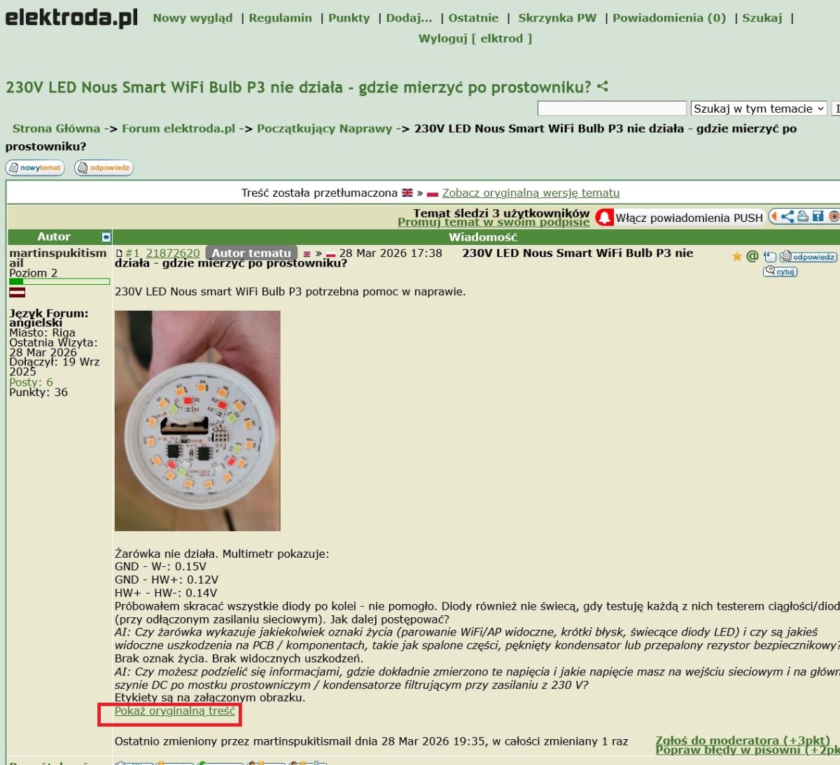
@martinspukitismail I'm curious if on your computer my message shows up in full or just an excerpt and the rest only shows up when you click on the "Show original content" option? Please write back. With me, this is how your topic shows up:
And I don't always get the idea of clicking on the aforementioned option at the bottom left of the screen....
Aluminum-backed LED board confirmed with white coating
As for the LEDs, my question is whether the board on which they are soldered on the other side is aluminium or some kind of plastic?
Thank you, elektrod. I'll follow your advice.
The LED board is mainly aluminum with a white layer (plastic or paint) on top.
Added after 6 [minutes]:
elktrod wrote:
I'm curious if on your computer my message shows up in full or just an excerpt and the rest only shows up when you click on the "Show original content" option?
A 230V LED Nous Smart WiFi Bulb P3 is non-functional with no visible damage or signs of life such as LED illumination or WiFi pairing signals. Voltage measurements between ground and LED terminals show very low voltages (~0.12-0.15V). Individual LEDs tested with a multimeter diode function do not light up, and shorting LEDs does not restore function. The power supply and control circuitry, including 8-pin ICs (U1 and U2), are suspected areas for further diagnostics. It is recommended to use a specialized LED tester (0-320V, preferably yellow) to verify LED integrity, noting that 2-pin LEDs differ from 4-pin programmable LEDs in testing methods. Identifying ICs via datasheets can guide measurement points and expected supply voltages. The missing power supply and control section may be the root cause of failure. AI summary based on the discussion. May contain errors.