logo elektroda
logo elektroda
X
logo elektroda

Fault Detection & Repair: LED Drive for Downlight & E14 Device, SMD Resistor & Capacitor Issues

ferbulous 804 7
ADVERTISEMENT
  • #1 20718316
    ferbulous
    Level 18  
    Hi, I have these devices that's not working

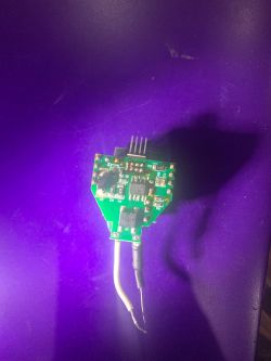
    LED drive for Downlight:
    The highlighted smd resistor appears to be damaged, the number marking was gone so I just assumed it could be 155 based on the nearby resistors. After replacing it, it's still not working.
    Electronic board with components, marked damage

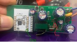
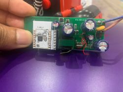
    E14:
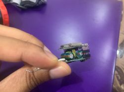
    I replaced the 16v 220uf capacitor and was able to get it running again but not for this one, seems like the capacitors are intact/not damaged.
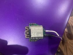
    ESP-12S module on a purple background with white wires.
    Person holding a small electronic module with visible capacitors.LED driver board with components on a purple background.

    Could anyone advice how I should start checking the components using the multimeter for fault?
    Do let me know if I need to provide more photos.
  • ADVERTISEMENT
  • #2 20718367
    p.kaczmarek2
    Moderator Smart Home
    Well, first I would check whether 3.3V is present at the WiFi module. Then I would check if WiFi module works to narrow the issue down to the LED driver. Then check which LED driver is used and find datasheet for it.

    Your description seems a bit confusing to me. It seems that you are repairing two of them, and one is fixed, but second is still not working?

    Also, how was it damaged? Maybe a cold solder joint?

    How the base of capacitors look like? See:
    https://www.elektroda.pl/rtvforum/topic3898805.html
    Open the link, you will see how damaged capacitor in smart device power supply looks like.
    Helpful post? Buy me a coffee.
  • ADVERTISEMENT
  • #3 20718388
    ferbulous
    Level 18  
    p.kaczmarek2 wrote:
    Well, first I would check whether 3.3V is present at the WiFi module. Then I would check if WiFi module works to narrow the issue down to the LED driver. Then check which LED driver is used and find datasheet for it.


    The wifi module works, i was still able to flash openbeken and it boots up after desoldering the chip (led driver downlight).
    By the way this downlight is using PWM led's.

    p.kaczmarek2 wrote:
    Your description seems a bit confusing to me. It seems that you are repairing two of them, and one is fixed, but second is still not working?

    Sorry about that, what I meant I have 2 units of E14 that's not working. The fist one had an obvious capacitor issue (bulging for 16v 220uf) and replacing the capacitor fixed it, but the second E14 had no issues with the capacitor.
  • ADVERTISEMENT
  • #4 20718392
    p.kaczmarek2
    Moderator Smart Home
    If you had capacitor issue, then it means PowerSave has to be enabled.

    How do you know that second one capacitor is okay? It may be degraded even if it's not visible from the outside. Have you checked with ESR meter?
    Helpful post? Buy me a coffee.
  • #5 20718407
    ferbulous
    Level 18  
    p.kaczmarek2 wrote:
    If you had capacitor issue, then it means PowerSave has to be enabled.

    Is this for the downlight? When I soldered the chip back, it doesn't boot up which might indicate there's no 3.3v on the pcb

    p.kaczmarek2 wrote:
    How do you know that second one capacitor is okay? It may be degraded even if it's not visible from the outside. Have you checked with ESR meter?

    I did also replace the 2end E14 with a new 16v 220uf capacitor but it's still not working.
  • #6 20723186
    p.kaczmarek2
    Moderator Smart Home
    Please carefully check with multimeter. We need to know where the fault is.
    Helpful post? Buy me a coffee.
  • ADVERTISEMENT
  • #7 20723242
    ferbulous
    Level 18  
    p.kaczmarek2 wrote:
    Please carefully check with multimeter. We need to know where the fault is.


    Hi, what’s the proper way of checking with multimeter?
    Does the device need be connected to the ac?
    I don’t really have a proper power supply so I’d need to find some other way to inject voltage?
    Do i set the multimeter mode to continuity or resistance?
    What values should i expect when there’s a short? Is it dependant on the component
  • #8 20723970
    ferbulous
    Level 18  
    Using this as reference


    I don't have the short circuit detector like in the video
    I do have 5v 10a & 12v 10a power supply brick that use for my led strip
    Should I inject voltage by connecting live and neutral from the power brick to the pcb?
    Set the multimeter in continuity mode then probe gnd (black probe) and the red probe to each component?
    How do I find other gnd points on the pcb?

    Close-up of a circuit board with marked electronic components.

Topic summary

The discussion revolves around troubleshooting two non-functional devices: an LED drive for a downlight and an E14 light fixture. The user initially replaced a damaged SMD resistor in the LED driver but the device remained non-operational. They confirmed the WiFi module is functional, indicating the issue lies with the LED driver. For the E14, a bulging capacitor was replaced, restoring functionality to one unit, while the second unit showed no visible capacitor damage. Participants suggested using a multimeter to check for faults, emphasizing the importance of verifying capacitor integrity with an ESR meter, and provided guidance on testing methods, including continuity and resistance settings. The user inquired about proper multimeter usage and voltage injection techniques for further diagnostics.
Summary generated by the language model.
ADVERTISEMENT