
logo elektroda
logo elektroda
X
logo elektroda

Kapsch OBU-4041, how the transport toll system works

p.kaczmarek2 1338 4

TL;DR

  • Kapsch OBU-4041 is a truck-mounted on-board unit for electronic toll collection, with a single button and axle-count LEDs for 2, 3, and 4 axles.
  • Inside, the board is minimal: one unknown IC with a quartz resonator, a buzzer, a button, LEDs driven through transistors, and microwave antennas on the reverse side.
  • It runs from a Tadiran 3.6V lithium battery, and the controller marking reads '68535 09899 D2L899 1225'.
  • A single beep means correct toll collection, two beeps warn of low pre-pay balance or low battery, and four beeps mean the toll was not paid.
  • The battery looks non-replaceable, so the unit is probably disposable, and the receiver-side processing remains unknown.
AI summary based on the discussion. May contain errors.
ADVERTISEMENT
Treść została przetłumaczona polish » english Zobacz oryginalną wersję tematu
📢 Listen (AI voice):
  • Kapsch OBU-4041, how the transport toll system works
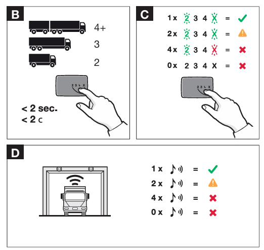
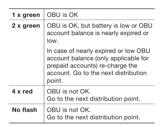
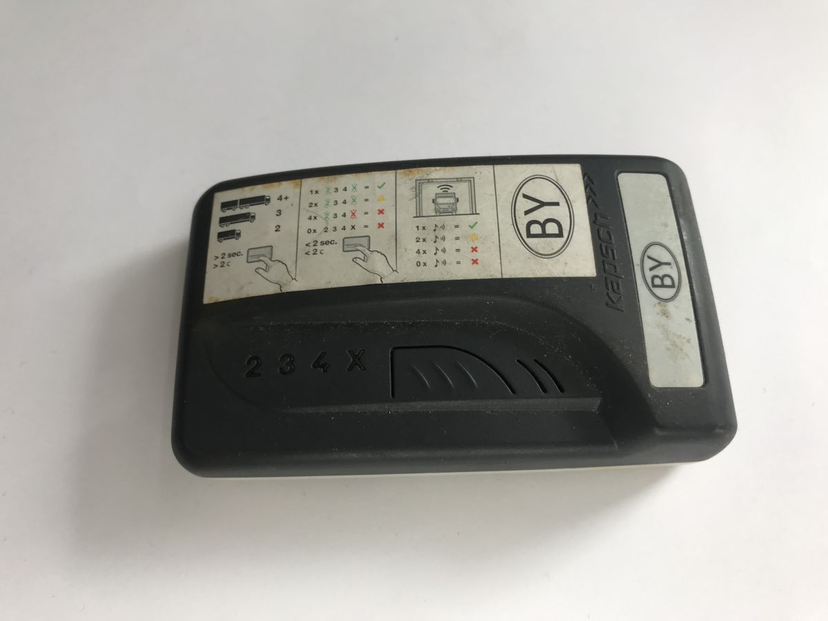
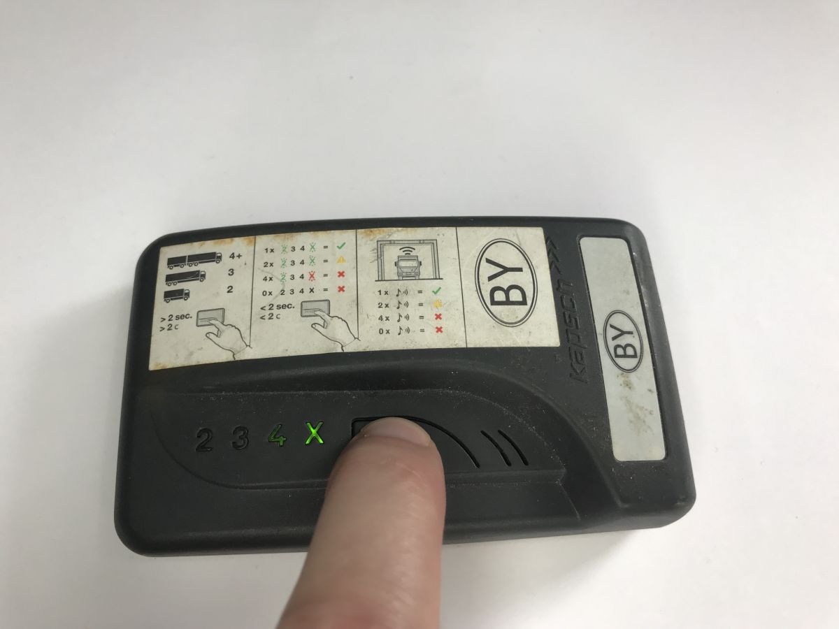
    Today we are taking a look inside another automotive device, more specifically the Kapsch OBU-4041 (On-Board Unit). At first glance, it is an inconspicuous box with a single button, mounted on the windscreen of a truck. Its purpose is to interface with electronic toll collection systems. On the front, there is a single button which, when pressed for a long time, is used to select the number of axles; a short press shows the current setting. The separate numbers 2, 3 and 4 are illuminated by LEDs. Correct selection is the responsibility of the driver. The specific method of use is well illustrated by a sticker on the device itself:
    Kapsch OBU-4041, how the transport toll system works
    Kapsch OBU-4041, how the transport toll system works
    Kapsch OBU-4041, how the transport toll system works Kapsch OBU-4041, how the transport toll system works
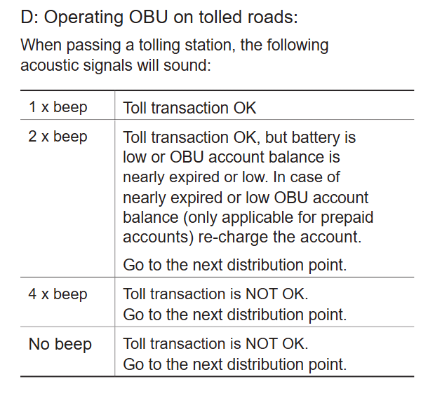
    A separate issue is the passage through the toll station. Communication is via an antenna mounted on a gantry above the toll road section. The driver is informed of correct toll collection by an audible signal. The device can operate in two modes: pre-pay and post-pay, depending on the contract concluded. A single beep indicates correct toll collection, two beeps indicate a low pre-pay account balance or low battery, and four beeps indicate that the toll has not been paid. If the toll is not collected, the system automatically takes a picture of the vehicle and sends it to the highway patrol after verification.
    Kapsch OBU-4041, how the transport toll system works
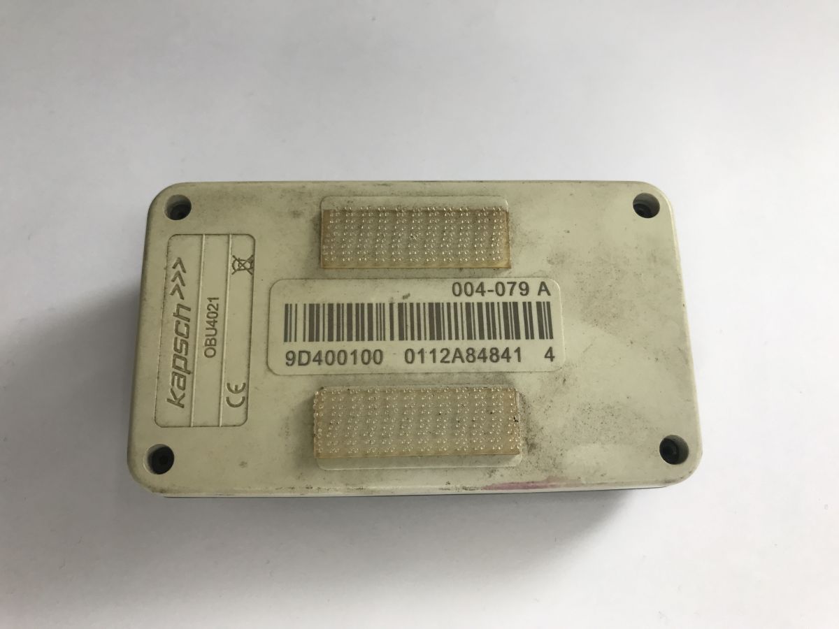
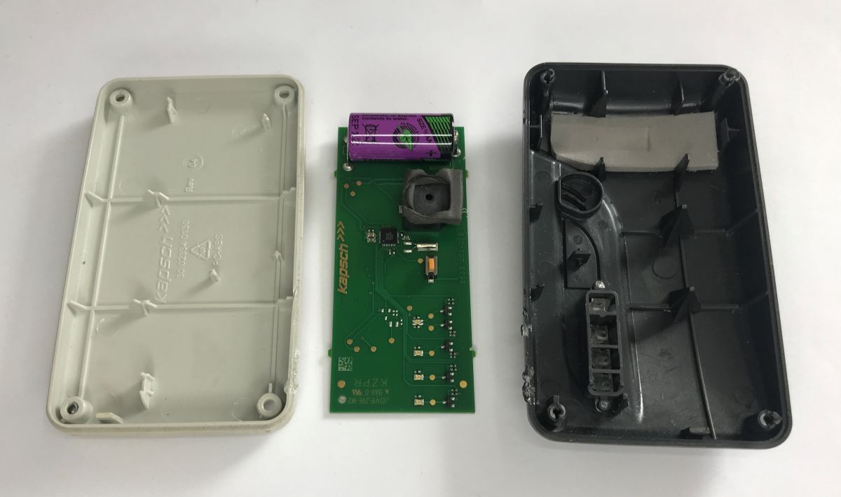
    Time to look inside. I thought it was the screws in the corner, but they look more like rivets. I broke out the housing.
    Kapsch OBU-4041, how the transport toll system works
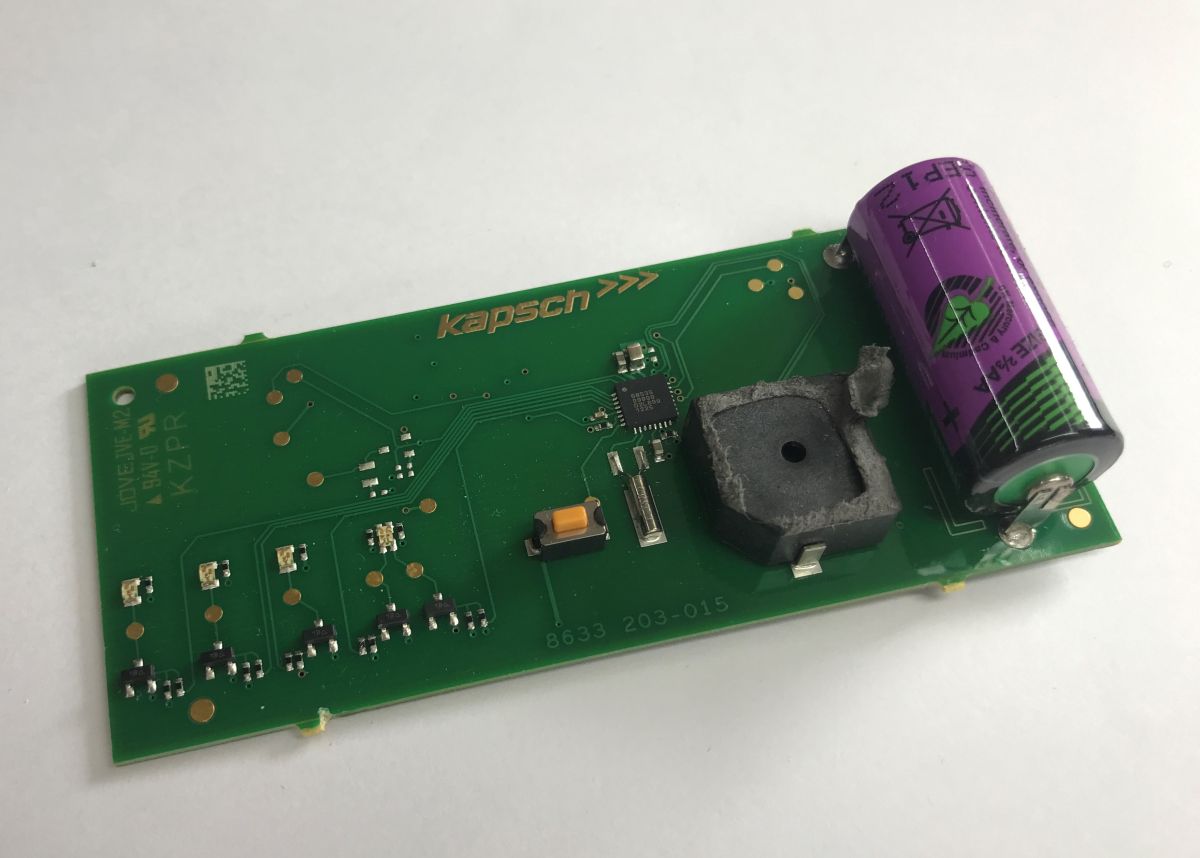
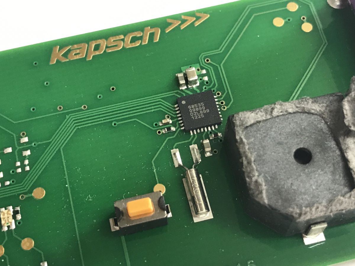
    The board is simple - battery, buzzer, one IC with a quartz resonator, the aforementioned button, and, well, LEDs - interestingly, each with a transistor.
    Kapsch OBU-4041, how the transport toll system works
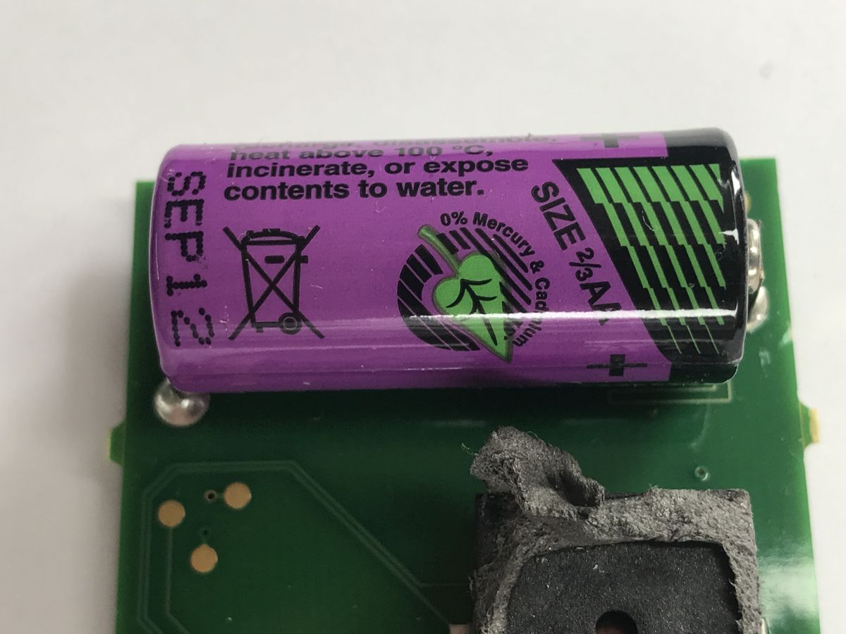
    The battery used is a Tadiran 3.6V lithium battery, doesn't look replaceable at all. Presumably the whole thing needs so little power that it is disposable.
    Kapsch OBU-4041, how the transport toll system works
    The main controller is 68535 09899 D2L899 1225 I couldn't find any information about it, maybe someone reading will have better luck?
    Close-up of a Kapsch PCB with an IC, a push button, and a buzzer
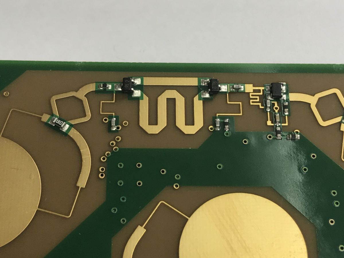
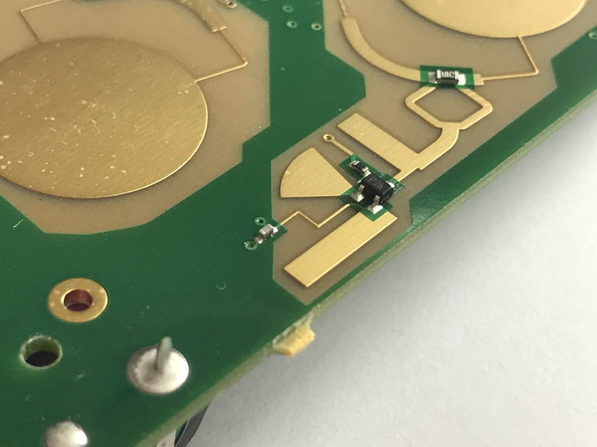
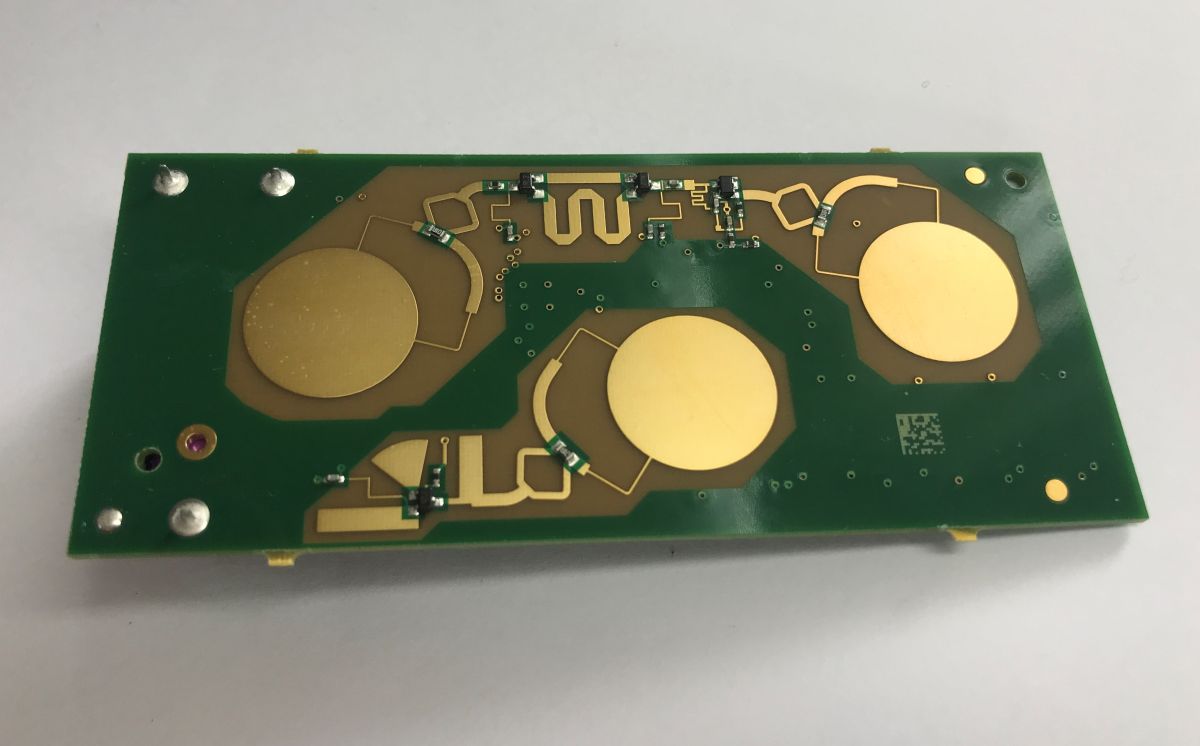
    The most interesting thing is from the other side - it looks like we have microwave antennas here:
    Green PCB with three large gold circular pads and gold traces, top view
    Close-up of a PCB with gold antenna traces and small SMD components Close-up of a PCB with antenna-like copper areas and small SMD components
    In summary, the Kapsch OBU-4041 is a very simple device for its application. Inside there is a single integrated circuit with a quartz resonator, a few discrete components, a buzzer, a button and LEDs to indicate the operating status. All the logic and operation of the device has thus been condensed to an absolute minimum, which suits its one specific task well. Probably the most interesting thing turned out to be the antennas. It's a pity I don't have access to the receiver, because then it would also be possible to see what further processes the requests - some kind of microcontroller, an SBC with GSM?
    So much for my part in this topic, if anyone is able to add more, please feel free to do so. By the way, I can recommend a related topic about the transmitter from Car Sharing .
    Do you use this type of module?

    Cool? Ranking DIY
    Helpful post? Buy me a coffee.

    About Author
    p.kaczmarek2
    Moderator Smart Home
    Offline 
    p.kaczmarek2 wrote 14728 posts with rating 12814, helped 659 times. Been with us since 2014 year.
  • ADVERTISEMENT
  • #2 21916915
    TechEkspert
    Editor
    Posts: 7287
    Help: 17
    Rate: 5666
    I suspect that under the gantry the field strength is high enough to induce a voltage in the detector and wake up the microcontroller and transciver, perhaps the data transmission is at a different frequency to the signal waking up the device?
  • ADVERTISEMENT
  • #3 21917325
    szymon122
    Level 38  
    Posts: 4092
    Help: 302
    Rate: 757
    p.kaczmarek2 wrote:
    The most interesting is from the other side

    My curiosity is always triggered when I see such shapes that have an "electronic" function in addition to their interesting appearance.
    Do any of you have any leads on an abridged article on this subject?
    I'd love to know the function of a "path departing cone" without studying RF circuits in their entirety :D
  • ADVERTISEMENT
  • viaTOLL device issues with battery and metallised windshields

    #4 21918388
    zozur
    Level 11  
    Posts: 24
    Such devices operated the viaTOLL toll system in Poland, which is now no longer in force. Problems included a non-replaceable battery and the need to drive off the toll road in the event of a breakdown of the device, the lack of readability of some toll gates and complaints and letters from ITD related to this. The device did not work properly if the vehicle windscreen had a metallised layer, in which case it had to be replaced with another device with an external antenna.
  • Possible microwave patch antennas and OOK oscillator layout

    #5 21918577
    olelek
    Level 24  
    Posts: 581
    Help: 62
    Rate: 167
    p.kaczmarek2 wrote:
    In summary, the Kapsch OBU-4041 is a very simple device

    Thank you for presenting the device. I am not from the industry myself, so I was not even aware of the technical solutions of the Viatoll system.
    Personally, I would say that the device is complex, just very cost optimised.
    It would be great to know the geometrical dimensions of the structures, for example the diameter of the antennas or the lengths of the transmission lines coming off the Wilkinson divider. The operating bandwidth could then be estimated, and compared with the Viatoll information.

    szymon122 wrote:
    My curiosity is always triggered when I see such shapes that have an "electronic" function in addition to their interesting appearance.
    Do any of you have any leads on an abridged article on this subject?
    I'd love to know the function of a "path departing cone" without studying RF circuits in their entirety


    I'll try my hand at deciphering the circuit, maybe fellow forum members can help.
    We see a resin coloured laminate, meaning a classic FR-4 was used here, or at most a low loss Isola type laminate (which I doubt if the aim was to keep costs down as much as possible), not any Teflon or Rogers.
    We have 3 microwave patch circular antennas connected via a classic Wilkinson divider. Why powered antennas like this? I don't know, maybe in order to work in both polarisations at the same time - in one polarisation the antenna works in a 90 degree phase shift relative to the other polarisation.
    I'm assuming the structure in the middle is the transmitter, you can see the bias tee, transistor / amplifier. The fan-shaped structure is either a capacitance or an LC circuit. At the output of the transistor you see another 'rectangle'. The whole thing forms an oscillator with modulation probably OOK type.
    The two external antennas seem to me to constitute the receiver circuit. Here I find it more difficult to decipher the circuit, but there is probably some sort of mixer here.
📢 Listen (AI voice):

FAQ

TL;DR: This FAQ explains a 3.6V Kapsch OBU-4041 for truck tolling. “The board is simple,” with one IC, one button, LEDs for 2, 3, and 4 axles, a buzzer, and PCB antennas. It helps drivers and electronics readers understand axle setting, beep meanings, and what happens when toll collection fails. [#21916832]

Why it matters: Toll charging depends on correct axle selection and successful gantry communication, so a simple device can still create billing and enforcement problems.

Option How payment works What the driver hears Main risk mentioned
Pre-pay Toll is charged against a prepaid balance 1 beep = paid, 2 beeps = low balance or low battery, 4 beeps = unpaid Balance can be too low
Post-pay Toll is charged under a contract after passage 1 beep = paid, 4 beeps = unpaid Failed collection still triggers enforcement

Key insight: The hardware is minimal, but the billing result is not automatic. The driver must set 2, 3, or 4 axles correctly before passing the gantry.

Quick Facts

  • The unit has a single front button and three axle indicators labeled 2, 3, and 4, so the driver can select the billing class directly on the windscreen-mounted device. [#21916832]
  • Audible feedback uses three distinct outcomes: 1 beep for correct toll collection, 2 beeps for low pre-pay balance or low battery, and 4 beeps when the toll is not paid. [#21916832]
  • Inside, the board carries one main IC, one quartz resonator, one buzzer, one button, several discrete parts, and separate transistors for the LEDs. [#21916832]
  • Power comes from a Tadiran 3.6V lithium battery that does not look user-replaceable, which points to very low-power, long-term operation in a sealed module. [#21916832]

How does the Kapsch OBU-4041 communicate with the toll gantry during electronic toll collection?

The Kapsch OBU-4041 communicates with an antenna mounted on a gantry above the tolled road section. The thread shows that the driver receives an audible confirmation after passage, which means the link completes quickly during the drive-by event. Photos of the PCB also show microwave-looking antennas on the board, consistent with short-range radio communication between the windscreen unit and roadside equipment. [#21916832]

What do the one, two, and four beep signals mean on a Kapsch OBU-4041 toll device?

One beep means the toll was collected correctly. Two beeps mean either the pre-pay balance is low or the battery is low. Four beeps mean the toll was not paid. Those three sound patterns give the driver immediate status feedback while passing the gantry, without needing a display. [#21916832]

How do you change and check the axle count setting on the Kapsch OBU-4041 using its single button?

You use the single button to set and verify the axle count. 1. Press and hold the button to change the setting. 2. Press briefly to show the current setting. 3. Read the lit LED for 2, 3, or 4 axles. The thread states that correct selection is the driver's responsibility, so this step directly affects billing. [#21916832]

What is an OBU in a truck toll system, and what does the Kapsch OBU-4041 actually do?

"OBU" is an on-board unit that handles toll-system communication inside the vehicle, using a compact, windscreen-mounted module to exchange status and billing data with roadside equipment. In this case, the Kapsch OBU-4041 lets the driver set 2, 3, or 4 axles, communicates at the gantry, and signals collection status with beeps. [#21916832]

What is the difference between pre-pay and post-pay modes in the Kapsch OBU-4041 toll system?

Pre-pay uses stored balance, while post-pay works under a contract after passage. The thread names both modes explicitly. It also links the 2-beep warning to low pre-pay balance or low battery, which makes balance monitoring a pre-pay-specific issue in the described behavior. [#21916832]

Why does the Kapsch OBU-4041 have separate LEDs for 2, 3, and 4 axles, and how is the setting used for billing?

It has separate LEDs so the driver can see the selected axle class instantly. The thread shows dedicated indicators for 2, 3, and 4 axles and says the driver must choose correctly. That setting matters because the toll system uses the selected axle count when the vehicle passes the gantry and the charge is assessed. [#21916832]

What happens in the toll system when the Kapsch OBU-4041 does not pay the toll correctly?

The system records the vehicle and escalates the case. The thread says that if toll collection fails, the system automatically takes a picture of the vehicle and, after verification, sends it to the highway patrol. The driver also hears 4 beeps, which marks the failure immediately at the roadside. [#21916832]

Which integrated circuit is marked 68535 09899 D2L899 1225 in the Kapsch OBU-4041, and where can I find documentation for it?

The thread does not identify that IC or provide documentation for it. It only reports the marking "68535 09899 D2L899 1225" and states that no information was found. In this discussion, the part remains undocumented, so there is no cited datasheet, vendor page, or confirmed function block for that package. [#21916832]

Why does the Kapsch OBU-4041 use a non-replaceable Tadiran 3.6V lithium battery, and how long is it expected to last?

The thread presents the 3.6V Tadiran lithium cell as a sealed, non-user-replaceable power source for a very low-power device. It says the battery "doesn't look replaceable at all" and treats the unit as effectively disposable. The expected lifetime is not stated anywhere in the posts, so the thread does not support a numeric service-life estimate. [#21916832]

What are the microwave-looking PCB antennas inside the Kapsch OBU-4041, and what frequency range do they likely use?

They are PCB antenna structures used for the toll radio link, but the thread does not give a measured frequency range. The teardown explicitly points to "microwave antennas" on the reverse side of the board, and the unit communicates with a gantry antenna overhead. No frequency value, band label, or RF measurement appears in the posts. [#21916832]

How do you safely open a Kapsch OBU-4041 housing that appears riveted without destroying the internal PCB?

The thread does not show a non-destructive opening method. It says the corner fasteners looked more like rivets than screws, and the housing was broken open. That means the discussion documents a teardown result, not a safe service procedure for preserving the original enclosure. [#21916832]

Why does each LED in the Kapsch OBU-4041 have its own transistor instead of being driven directly from the main IC?

The thread confirms the separate transistors, but it does not give the design reason. It notes that each LED has its own transistor and that the board is otherwise very simple, with one main IC and a quartz resonator. Without a schematic or IC documentation, the exact purpose of those transistor stages stays undocumented here. [#21916832]

Could the toll gantry field wake up the Kapsch OBU-4041 by induction before data transmission starts, and how would that work in practice?

Yes, the thread presents induction wake-up as a plausible operating sequence. A reply suggests that the gantry field could be strong enough to induce voltage in the detector and wake the microcontroller and transceiver, while actual data transmission could then use a different frequency. That is a technical hypothesis from the discussion, not a confirmed measurement. [#21916915]

How does a DSRC-style toll transponder like the Kapsch OBU-4041 compare with GNSS or GSM-based toll collection systems?

The thread only describes a gantry-based transponder, not a GNSS or GSM toll system. It shows a local interaction between the windscreen OBU and an antenna above the road section, with immediate beep feedback during passage. Because the posts do not discuss satellite positioning, cellular backhaul in the vehicle, or app-based billing, no fuller comparison is supported here. [#21916832]

What electronics are typically installed on the toll gantry or backend receiver that talks to the Kapsch OBU-4041 and verifies payment?

The thread confirms a gantry antenna and an enforcement camera path, but it does not identify the exact receiver hardware. It says communication happens via an antenna mounted on the gantry and that failed tolls trigger an automatic vehicle photo sent to highway patrol after verification. The author only speculates about a microcontroller, SBC, or GSM-connected backend, so those parts are not confirmed. [#21916832]
AI summary based on the discussion. May contain errors.
ADVERTISEMENT