logo elektroda
logo elektroda
X
logo elektroda

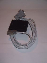
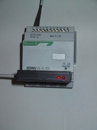
EASY 512-DC-R Driver: Creating DIY EASY-PC-CAB (Moeller) Cable with MAX232 Schematic

Myrek1 50727 29
ADVERTISEMENT
Treść została przetłumaczona polish » english Zobacz oryginalną wersję tematu
  • #1 2451524
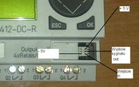
    Myrek1
    Level 23  
    Hello.
    I got the EASY 512-DC-R driver. I want to learn it. I have a PC software but I miss a cable. I thought to myself that I would make it myself because it is probably a simple cable on some MAX232. Do you have a schematic of such a cable (EASY-PC-CAB)?

    best regards
  • ADVERTISEMENT
  • #2 5729702
    felix12
    Level 11  
    I bought such a cable from Moeller and took it apart. There are only 2 optocouplers and a pair of resistors and transistors inside, so it is only used for galvanic isolation. If someone wants to, I will draw this diagram, it looks like it is enough to track which pin is from TX and which is RX and simply connect using pins.
  • #3 5808164
    dydymo
    Level 11  
    Come on, a few zlotys for a cable and you try to figure out how to do it so as not to pay a few pennies. There you have a "flooded", read the more durable RS plug on the other side, the relay plug, which holds well in the relay, does not fall out when accidentally pulled, always fits, does not crumple the pins when inserting and you want to do a good job without a good tool? It has been known for a long time that it does not pay off in the long run.

    best regards
  • ADVERTISEMENT
  • #4 5816758
    mirben
    Level 22  
    Hello !
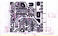
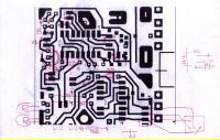
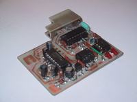
    I do not have the original schematic, I never managed to get it. I made my own system from standard components. Everything was invented, including the board, so that it could even be produced. Until today, the price is probably over PLN 160. The project is somewhere among other materials, unfortunately I don't have it on my computer. Today I can only present two photos of the made layout, that's what I found. Electronics are two optocouplers and MAX 232, but the better one is probably 3232, because as I remember, this cheap had problems on some coms in several computers. The biggest problem is making the plug to the controller. Need a lot of precision, small pins and a strange spacing. I have not found any ready with these parameters, it is about the plug. This is what Moeller's "trick" is about, such a limitation, because electronics is a classic transition from COM to Cmos with galvanic isolation. I will look for materials from this construction and make it available to the "world".
    EASY 512-DC-R Driver: Creating DIY EASY-PC-CAB (Moeller) Cable with MAX232 Schematic
    EASY 512-DC-R Driver: Creating DIY EASY-PC-CAB (Moeller) Cable with MAX232 Schematic
  • #5 5887708
    mirben
    Level 22  
    I present below schemas of diagrams and boards for Moeller transmission cable. Sorry, but until today, since fall 2006, I haven't found time to make clean drawings, there just wasn't good motivation. It only has working notes. I remember that I spent a lot of time testing the reliability of this design and sold a dozen or so copies. They have an advantage over the original blind cable because they use LEDs to show the transmission movement.
    The interface diagram for the Siemens Logo served me as an "exit" on which I based my design. I used the best of the cheapest 6N136 optocouplers. Unfortunately, it is impossible to save on the MAX 3232, as I mentioned earlier. The popular 232 does not want to work with every computer. Large spread of IC parameters that support RS 232 outputs. Later PDF board will be included (note the copper side mounting) and some additional photos of the finished cable.

    EASY 512-DC-R Driver: Creating DIY EASY-PC-CAB (Moeller) Cable with MAX232 Schematic

    Added after 34 [minutes]:

    Tmp 2 - arrangement of elements on the board
    Tmp 3 - interface diagram for Logo
    Tmp 4 - my cable diagram
    Tmp 5 - working diagram of the board
    Tmp 7 - dimensioned parameters of the joint. Its second plate is obtained by cutting off the corner of the base plate.

    For an amateur used cable, it is recommended to use 3 pieces (several centimeters each) of cables terminated with wire from RJ connectors, e.g. from a broken network switch or telephone socket.
  • #6 5887967
    mirben
    Level 22  
    Ps. in the drawing showing the arrangement of elements on the board, the integrated circuits are incorrectly marked as to the location. 4049 and 232 - the opposite is what I described.
  • #7 5896027
    mirben
    Level 22  
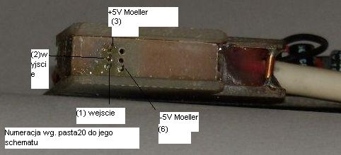
    This is how I based my design on the diagram created for the Siemens logo, using only slightly different components, you can say substitutes. I attach a more detailed photo of the partially assembled electronics (without the COM cable) and a view of the connector itself.
    EASY 512-DC-R Driver: Creating DIY EASY-PC-CAB (Moeller) Cable with MAX232 Schematic
    EASY 512-DC-R Driver: Creating DIY EASY-PC-CAB (Moeller) Cable with MAX232 Schematic
  • #8 5906393
    pasta20
    Level 15  
    A few more corrections and I will put the schematic in the library together with the library :D

    Regards and please wait a moment :D

    Do you have any patterns, give it; D

    so I put files to the protel program with the library.

    // Corrected diagram, power supply from the easy driver side, not from pc
  • #9 5924982
    mirben
    Level 22  
    Hello !
    I have never tried the original Moeller cable. I didn't, because it was always too expensive for me. Apart from a simple mistake that may occur in the diagram, e.g. whether the plug or socket is drawn and from which side, not everyone describes such things well, you should be aware that the signal voltage levels should be stable and appropriate. And what Moeller used in his cable on the driver side, unfortunately, I do not know. Apparently some transistors. Whether they can work well with, for example, some resistors connected by Siemens in the Logo, it is difficult for me to say. The drawing, (diagram) TMP3 has never been verified by me with the Logo driver, I am not its author. Two legs from such a connector can be verified with a voltmeter, they should be the power supply, i.e. plus and minus 5V. Maybe the output with the input can be distinguished, the output should take one of the two states 0 or 1. And the input can be with a transient state if they have not attached a resistor to it. Personally, to recognize Moeller, I undressed him and figured out what is what along the paths.
    Finally, something can always be mixed up in the settings of the program that handles all this, eg bits for COM. My design was able to deal with Moeller at max speeds.
    And by the way, Siemens went even further in "miracle" the connector in its Logo, what the customer would pay for the cable 75 euros. And what a beautiful world would be if all drivers used, say, a standard RJ.
  • #10 5948595
    lok56
    Level 12  
    Hello!
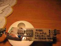
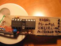
    And I am adding my "clunky" but working zelio cable
    and alpha
    EASY 512-DC-R Driver: Creating DIY EASY-PC-CAB (Moeller) Cable with MAX232 Schematic
    EASY 512-DC-R Driver: Creating DIY EASY-PC-CAB (Moeller) Cable with MAX232 Schematic
    EASY 512-DC-R Driver: Creating DIY EASY-PC-CAB (Moeller) Cable with MAX232 Schematic

    if I buy a logo, I will try and with the logo.
  • #11 6613885
    pasta20
    Level 15  
    I did it in the altium.
    Someone can write the easy 412-DC-R plug
    Because the schematic should be correct.

    Best regards.
  • ADVERTISEMENT
  • #12 6691620
    mirben
    Level 22  
    Adding some information to the above, a photo of Moeller's nest.
    "Another Fairy Tale"
    Recently, I had to obtain an interface to the gas computer in my car. I figured I would adopt the circuit shown here quickly, I insisted it had optoisolation.
    I am not a practicing electronics technician. Almost three years that have passed since the experiences described above meant that I forgot about the problems with powering the MAX 232 from Com (inefficient). That's why I preferred the MAX 3232.
    Now I had one copy of the 232. After many hours of "fighting" I couldn't get some interface working. Resigned, I decided on the so-called prosthesis. I powered the Max 232 from the USB socket, creating a bridge between the Com and USB plugs.
    It is not an elegant solution, but I describe it here because in my case I needed efficiency and the interface implementation time was valuable. Maybe someone will be in a similar situation, so they will take advantage of the opportunity I have described.
    I wish you successful constructions.
    EASY 512-DC-R Driver: Creating DIY EASY-PC-CAB (Moeller) Cable with MAX232 Schematic
  • #13 8074090
    elmer-83
    Level 13  
    Hello
    I have three questions:
    1.can someone post a normal connection diagram between RS port and easy ?? means which pin in RS to which pin in easy-ku. \
    2. Do you know how to control the falling slope in easy 619-dc-rc ??: /
    I have been combining for a few hours. and there is probably no such possibility: / at least not from the keyboard: / Lipa because he needs to control the falling slope: /
    3. Is it normal that when I refer to the same output in two program lines, it doesn't work ??: / NP:
    I1 ------- Q1
    I2 ------- Q1 Something like this does not activate when giving a signal to I1, only I2 works

    and at:

    I1 ------- Q1
    I2-- | When I2 is bridged with the signal from I1, both inputs work: /

    best regards
  • #14 8074243
    ploteklotek
    Level 11  
    Quote:
    1.can someone post a normal connection diagram between RS port and easy ?? means which pin in RS to which pin in easy-ku.


    I don't think I understood the question. You can't directly connect the EASY pins to the computer's RS input.? You need a minimum RS232 voltage converter. Anyway, the schematics are given in this thread, e.g. the TMP3.JPG file in the mirben user post.

    Quote:
    2. Do you know the way to control the falling slope in easy 619-dc-rc ??: I have been working for a few hours. and there is probably no such possibility: at least not from the keyboard: Lipa because she needs to control the falling slope:


    Maybe yes:

    I01 ------ SM01
    M01- / I01 - SQ01
    .............. |
    ...............- RM01

    There is still the problem of how to reset the output.

    Quote:
    3. Is it normal that when I refer to the same output in two program lines, it doesn't work ??: / NP:
    I1 ------- Q1
    I2 ------- Q1 Something like this does not activate when giving a signal to I1, only I2 works

    and at:

    I1 ------- Q1
    I2-- | When I2 is bridged with the signal from I1, both inputs work: /


    In my opinion, this situation is normal, because the driver executes the program line by line. So in the situation
    I1 ------- Q1
    I2 ------- Q1

    if I1 is turned on, information about turning on Q1 is saved for a moment in the memory cell of the controller's outputs. If I2 is turned off, moments later, in the same memory location, the information about turning off the Q1 output is written to the same memory location.
    At the end of the cycle, when the contents of the appropriate memory cells are copied to the outputs, the situation is when Q1 is turned off.
  • #15 8075778
    elmer-83
    Level 13  
    Hello

    Quote:
    I don't think I understood the question. You can't directly connect the EASY pins to the computer's RS input.? You need a minimum RS232 voltage converter. Anyway, the schematics are given in this thread, e.g. the TMP3.JPG file in the mirben user post.


    I used to have such a cable and I did not think that they packed so much electronics in the RS socket: /

    Quote:
    Maybe yes:

    I01 ------ SM01
    M01- / I01 - SQ01
    .............. |
    ...............- RM01

    There is still the problem of how to reset the output.


    Lipa that you cannot simply assign input I or output Q to react to the falling edge: / I did a little differently, on the counter and it also works, but both ways have to be deleted and it costs lilies of text and tags: / But thanks for the hint anyway

    Quote:

    I1 ------- Q1
    I2 ------- Q1


    From what I remember, on another easy-k, also from the 600 family, I wrote this way and it worked: / It seemed to me that the controller works like a typical wiring diagram, only written in the controller. The example I have given is basic. but the same is the case with time trials and counters: /

    And one more question beyond the competition :)
    Does anyone know where to buy an original 600 cable cheaply :)
  • #16 8168254
    bestler
    Admin of DIY, Automation
    I cleaned up the topic a lot and I close it.
  • #17 17058483
    Euphaz
    Level 1  
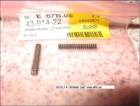
    I bought some EASY relays from ELFA and found a lot of useful information from your forum postings regarding the programming cable and the electronics. I am working on a schematic for the cable based on the information you provided at the forum, thank you for sharing. Regarding the strange connector, in my electronics collecting boxes I found some old 1.27 mm pitch header connectors i had bought from ELFA (see attached picture with item number and info) which actually fitted quite good regarding the dimension of the square pin (0.4 mm), and the pitch of the rows (1.27 mm) into the relay. But the dimention of the column spacing seems to be around 2 mm.

    I split my dual 1.27 x 1.27 header into single columns (very careful work using a sharp knife) and inserted the parts into the relay (see picture). Then I dropped two drops of epoxy in between the connector columns and the 1.27 x 2.00 mm connector is hopefully going to work.
  • #18 19642989
    pietrek345
    Level 15  
    mirben wrote:
    Adding some information to the above, a photo of Moeller's nest.
    "Another Fairy Tale"
    Recently I had to get an interface to the gas computer in my car. I figured I would adopt the circuit shown here quickly, I insisted it had optoisolation.
    I am not a practicing electronics technician. Almost three years that have passed since the experiences described above meant that I forgot about the problems with powering the MAX 232 from Com (inefficient). That's why I preferred the MAX 3232.
    Now I had one copy of the 232. After many hours of "fighting" I was unable to get some interface working. Resigned, I decided on the so-called prosthesis. I powered the Max 232 from the USB socket, creating a bridge between the Com and USB plugs.
    It is not an elegant solution, but I describe it here because in my case I needed efficiency and the interface implementation time was valuable. Maybe someone will be in a similar situation, so they will take advantage of the opportunity I have described.
    I wish you successful constructions.
    EASY 512-DC-R Driver: Creating DIY EASY-PC-CAB (Moeller) Cable with MAX232 Schematic

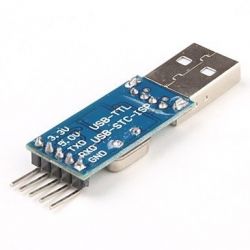
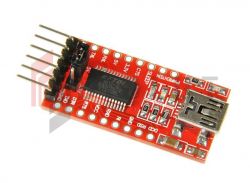
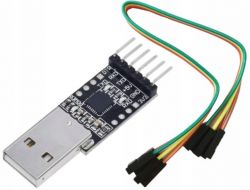
    Hello, I know that a lot of time has passed, but has anyone tried if it will work with a usb rs ttl adapter of this type:

    EASY 512-DC-R Driver: Creating DIY EASY-PC-CAB (Moeller) Cable with MAX232 Schematic
    connecting + 5V, GND, TxD, RxD?
  • #19 19669649
    lucastg
    Level 14  
    Hello, if this particular one works, I do not confirm but personally I have been using the red ft232rl for several years without any problems.


    EASY 512-DC-R Driver: Creating DIY EASY-PC-CAB (Moeller) Cable with MAX232 Schematic
  • #20 19669697
    pietrek345
    Level 15  
    I confirm the operation, after connecting the TxD RxD and GND
  • #21 19842470
    Codetrr
    Level 2  
    pietrek345 wrote:
    I confirm the operation, after connecting the TxD RxD and GND


    why can't I connect eas 512-AC-RCX?

    I use Prolific USB to serial. and connect
    RX - TX - GND.
  • #22 19846054
    pietrek345
    Level 15  
    Codetrr wrote:
    pietrek345 wrote:
    I confirm the operation after connecting TxD RxD and GND


    why can't the eas 512-AC-RCX connect?

    I am using a serial Prolific USB To. and connect
    RX - TX - GND.

    TTL?
  • #23 19855286
    Codetrr
    Level 2  
    pietrek345 wrote:
    Codetrr wrote:
    pietrek345 wrote:
    I confirm the operation after connecting TxD RxD and GND


    why can't the eas 512-AC-RCX connect?

    I am using a serial Prolific USB To. and connect
    RX - TX - GND.

    TTL?


    usb to ttl?
  • #24 19858926
    pietrek345
    Level 15  
    Yes. I've used one like this
    EASY 512-DC-R Driver: Creating DIY EASY-PC-CAB (Moeller) Cable with MAX232 Schematic
  • #25 19862725
    info_serwis
    Level 11  
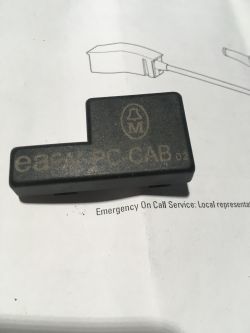
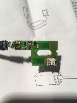
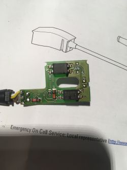
    Hello. I have the cable in question and I am posting a photo of what it looks like inside. However, I have a request. There is no plug on the PC side (DB9). Does anyone have a list of which color to which pin? Or at least how to track GND? Thank you in advance.


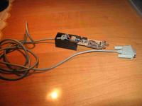
    EASY 512-DC-R Driver: Creating DIY EASY-PC-CAB (Moeller) Cable with MAX232 Schematic EASY 512-DC-R Driver: Creating DIY EASY-PC-CAB (Moeller) Cable with MAX232 Schematic EASY 512-DC-R Driver: Creating DIY EASY-PC-CAB (Moeller) Cable with MAX232 Schematic
  • ADVERTISEMENT
  • #26 19863218
    Telo
    Service technician RTV
    Hello

    It would be nice if you could draw a diagram of this tile to make it easier to identify the gnd.
  • #27 20343928
    Kacper.kacper
    Level 6  
    lucastg wrote:
    Hello, I do not confirm whether this particular one works, but I personally use the red ft232rl for several years without any problems.


    EASY 512-DC-R Driver: Creating DIY EASY-PC-CAB (Moeller) Cable with MAX232 Schematic


    The topic has long been out of date, but do we just connect the tx rx gnd to this converter and it works? And the question is whether different moellers have the same plug pinout? Regards
  • #28 21166494
    MarekGrzelczyk
    Level 6  
    >>6613885 Hello can someone make me such a cable for a 720 DC relay
    Greetings

    Added after 2 [minutes]:

    Can someone make me such a cable, for a fee of course for a 720 DC R relay reply by email masterso1702(_at_)gmail.com
    Regards
  • #30 21351034
    MarekGrzelczyk
    Level 6  
    I repeat the question of making such a cable contact masterso1702(_at_)gmail.com, for cash of course

    Added after 36 [seconds]:

    SMS contact 662210998

Topic summary

The discussion revolves around creating a DIY cable for the EASY 512-DC-R driver, specifically the EASY-PC-CAB, using a MAX232 or MAX3232 for RS-232 communication. Users share insights on the internal components of the original Moeller cable, which includes optocouplers for galvanic isolation. Several participants provide schematics and personal experiences with building their own cables, highlighting the challenges of connector pinouts and the need for precision in assembly. There are mentions of using USB to serial adapters and the importance of stable signal voltage levels. Some users express frustration with the cost of original cables and share alternative solutions, including custom designs and modifications to existing connectors.
Summary generated by the language model.
ADVERTISEMENT