logo elektroda
logo elektroda
X
logo elektroda

How do I properly upload ESP Easy to an ESP8266 module with a relay?

djecstasy 3285 26
ADVERTISEMENT
Treść została przetłumaczona polish » english Zobacz oryginalną wersję tematu
  • #1 17968689
    djecstasy
    Level 9  
    Hello
    I have an ESP2688 wifi module along with a relay:
    Link .
    I can't seem to get to grips with uploading ESP Easy to it.
    I connect to the laptop using a USB-UART RS232 converter PL2303HX (rather fake).
    5V power supply from the converter, RXD connected to TXD on the converter, TXD to RXD on the converter, GDN to GDN.
    After connecting the ESPlorer, the module is detected with baud rate set to 9600. When trying Chip Info I get ERROR.
    After running ModeMCU Firmware Programmer AP MAC and STA MAC is on Waiting MAC.
    I think I have something wrong with the connection but don't know what....
    The relay still has additional pins DAT, RST and CLK which according to the shop are used to program the MCU but I have not found any instuction using these pins anywhere.
    Anyone have any advice?
  • ADVERTISEMENT
  • #2 17968808
    BlueDraco
    MCUs specialist
    djecstasy wrote:
    Power supply 5V from converter
    .

    And all is clear...
  • #3 17968860
    djecstasy
    Level 9  
    I connected the mains supply via the power supply, the RXD with the TXD on the converter, the TXD with the RXD on the converter, the GDN with the GDN anda still the same....

    ESP Config shows a connection:
    AT+GMR AT version:1.2.0.0(Jul  1 2016 20:04:45)
    SDK version:1.5.4.1(39cb9a32)
    Ai-Thinker Technology Co. Ltd.
    Dec  2 2016 14:21:16
    OK
    .

    ModeMCU Firmare Programmer still "Waiting MAC".
  • #4 17969017
    khoam
    Level 42  
    BlueDraco wrote:
    djecstasy wrote:
    5V supply from converter
    .

    And all is clear...
    .
    This module with the relay just happens to be powered from 5V.

    Added after 34 [seconds]:

    Have you read the instructions for this module? Attached.
  • ADVERTISEMENT
  • #5 17969033
    djecstasy
    Level 9  
    Yes I have familiarised myself.
    The connection is shown exactly as I have it now.
    I can connect to the phone via WiFi. only it doesn't help me because I need to change the software to ESP Easy....
  • #6 17969048
    khoam
    Level 42  
    djecstasy wrote:
    I can connect to the phone via wifi. only it doesn't do anything for me because I need to change the software to ESP Easy...
    .
    Then you will unfortunately have to unplug the ESP-01 module from the whole thing and connect the ESP-01 directly to the USB/UART converter, but this time supplying the ESP-01 with 3V3 (also from the converter).
    There are many threads on the Forum on how such programming should be done.
  • #7 17969067
    djecstasy
    Level 9  
    Hmm... The converter I have has only 5V pulled out.
  • ADVERTISEMENT
  • #8 17969071
    khoam
    Level 42  
    Post a picture of this converter from above and we'll find out.
  • #9 17969125
    djecstasy
    Level 9  
    Ok I took the converter housing apart and there is indeed a 3V3 connector but the cable is not removed. So you have to solder from 5V to 3V3. Then connect the converter with esp8266 TXD to TXD, RXD to RXD and GDN to GDN and of course 3V3?
  • #10 17969132
    khoam
    Level 42  
    EDIT: corrected image
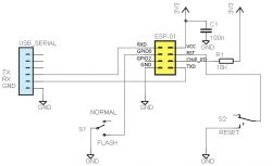
    How do I properly upload ESP Easy to an ESP8266 module with a relay? .

    Of course the 3V3 power supply also goes from the converter.
  • #11 17969679
    djecstasy
    Level 9  
    khoam wrote:
    EDIT: corrected image
    d60101fd1d5

    Of course the 3V3 supply also goes from the converter.
    .
    This schematic seems overcomplicated to me. Is there really no way to reprogram this ESP8266 without unplugging it? What are those extra DAT, RST and CLK pins for?
  • ADVERTISEMENT
  • #13 17969807
    djecstasy
    Level 9  
    khoam wrote:
    djecstasy wrote:
    What are those extra DAT, RST and CLK pins for?
    .
    I believe for programming the STC15F104W chip which is located in this module.
    .

    Ok then please explain it to me in a spatial way how it should be connected.
    From what I can see on the schematic all pins (except GPIO2) are connected and this is a requirement yes?
    TX to RX
    RX to TX
    3.3V power supply under pin 3V3 and CHIP_PD (in my case as EN)
    GDN under GDN GPIO0 (in my case as I00), and RST

    and all this via a converter ? It's a bit difficult to connect it all like that....
  • #14 17969826
    khoam
    Level 42  
    djecstasy wrote:
    TX to RX
    RX to TX
    3.3V power supply under pin 3V3 and CHIP_PD (on me as EN)
    GDN under GDN GPIO0 (in my case as I00), and RST
    .
    Correct. GPIO0 is shorted to GND when programming the chip (uploading firmware).

    djecstasy wrote:
    and this is all through the converter ?
    .
    You connect 4 wires to the converter from the ESP-01: RX, TX, 3V3 and GND.

    Added after 2 [minutes]: .

    djecstasy wrote:
    It's a bit difficult to connect everything like this...
    .
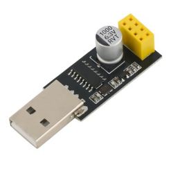
    An ESP-01 programming adapter is available for sale:

    How do I properly upload ESP Easy to an ESP8266 module with a relay? .
  • #15 17969866
    djecstasy
    Level 9  
    khoam wrote:
    djecstasy wrote:
    TX to RX
    RX to TX
    3.3V power supply under pin 3V3 and CHIP_PD (in my case as EN)
    GDN under GDN GPIO0 (in my case as I00), and RST
    .
    Correct. GPIO0 is shorted to GND when programming the chip (uploading firmware).

    djecstasy wrote:
    and this is all through the converter ?
    .
    You connect 4 wires to the converter from the ESP-01: RX, TX, 3V3 and GND.

    Added after 2 [minutes]: .

    djecstasy wrote:
    It's a bit difficult to connect everything like that...
    .
    An ESP-01 programming adapter is available for sale:

    How do I properly upload ESP Easy to an ESP8266 module with a relay?
    .

    OK thanks for the advice. In that case I need to purchase such an adapter.
    If the ESP8266 Config detects it as such then I understand the ESP8266 itself is not broken?
    Because I'm wondering if I've sometimes damaged the module through my attempts and whether to order a new one...
  • #16 17969876
    khoam
    Level 42  
    djecstasy wrote:
    Because I'm wondering if I've sometimes messed up the module by my attempts and whether to order a new one...
    .
    From post #3, it seems that you have not loosened the module so far .... probably ;)

    Added after 6 [minutes]:

    Before possibly purchasing a second same module: are you sure that this particular module with STC15F104W is supported by ESPEasy ?
    Of course I am not referring to the ESP-01 itself, in which case I have no doubts.
  • #17 17969966
    djecstasy
    Level 9  
    khoam wrote:
    djecstasy wrote:
    Because I'm wondering if I sometimes messed up the module by my attempts and whether to order a new one ...
    .
    From post #3, it appears that you have not loosened the module so far .... probably ;)

    Added after 6 [minutes]:

    Before possibly purchasing a second same module: are you sure that this particular module with STC15F104W is supported by ESPEasy ?
    Of course, I am not referring to the ESP-01 itself, in which case I have no doubts.

    It seems to be working:
    Link .
    I think I will purchase this converter along with a spare ESP8266 module alone
  • #18 17969997
    xury
    Automation specialist
    khoam wrote:
    are you sure that this particular module from STC15F104W is supported by ESPEasy?
    .
    It is supported. However, there is no support in the official builds. You have to compile it yourself or download the compiled bin from the letscontrolit forum.
    I personally have two of these and there were problems with both.
    The first one did not have the STC15F104W programmed and the resistors swapped. The second one was supposedly OK, but under 230V operating conditions it would reset every few seconds.
    I managed to get the first one working by uploading a batch to it. It works stably to this day. The second one, unfortunately, was unstable all the time, so I removed the STC15F104W from it and replaced it with some recycled optocoupler.
    Generally I do not recommend it. It's better to use ones controlled directly from the GPIO. The other issue is the low stability of the ESPEasy itself. I prefer the Tasmot. Well, unless sometimes it has to be EspEasy, then I use my compilations, from older sources.
  • #19 17970002
    khoam
    Level 42  
    djecstasy wrote:
    It seems to be working:
    Link
    .
    From this post, it appears that you need to slightly rework this module with the STC15F104W so that the ESP8266 can directly control the relay.
  • #20 17970012
    djecstasy
    Level 9  
    Now this is what has me dumbfounded....
    I need a 12v relay to control the solenoid valve. Do you recommend anything other than the one I purchased?
  • #21 17970013
    khoam
    Level 42  
    xury wrote:
    It is better to use such controlled directly from GPIO.
    .
    This is exactly what I meant, ESPEasy assumes direct relay control from the GPIO.
  • #22 17970025
    xury
    Automation specialist
    There is no need to rework, as long as you hit on a good piece. Control is via UART and this can even be achieved on the stock Espeasy thanks to Rules.
    The advantage of this, as long as it works stably, is that the ESP8266 reset does not affect the relay state. But it is the stability of the STC15F104W itself that is the problem
    this topic what you provided are also my posts.
    And in the letscontrolit forum too.
    As for uploading ESPeasy itself, I had no problems with my lctech module. I only needed to specify a low state on GPIO0 to put the ESP-01 into flash mode. I did this with a piece of wire just after pressing flash in the program.
    Sometimes it didn't work the first time, but it generally works. It is important to remember what conditions a board with ESP8266 must meet to be put into flash mode.
  • #23 17970292
    djecstasy
    Level 9  
    To summarise. The Esp8266 module itself is best programmed using the aforementioned adapter so that I don't have to short circuit anything else etc.
    As for the relay module itself, if the one I currently have is causing problems, what is the best one to use? I need one for 12v
  • #24 17970311
    xury
    Automation specialist
    Whether it causes problems you won't know until you program the Esp-01
  • #25 17971338
    djecstasy
    Level 9  
    OK the whole relay went down....
    In the converter plug the GDN cable broke off and shorted to 3v3 probably.

    Now I'm thinking of buying a ready-made sonoff and connecting it before the 12v power supply, but in order to connect it to the domoticz it needs to be reworked....
  • #26 17971425
    xury
    Automation specialist
    djecstasy wrote:
    OK the whole relay went down....
    A GDN cable broke off in the converter plug and shorted to 3v3 probably.
    .
    Eee surely it can be salvaged. Well unless the 12v went. ESP8266's are incredibly resilient to various incidents. More than once I forgot myself and powered the esp-01 from 5V. More than once I've run ground or VCC across the pins and haven't managed to fry any yet.
  • #27 17971445
    djecstasy
    Level 9  
    xury wrote:
    djecstasy wrote:
    OK the whole relay went down....
    A GDN cable broke off in the converter plug and shorted to 3v3 probably.
    .
    Eee sure it can be salvaged. Well unless the 12v went. ESP8266's are incredibly resilient to various incidents. More than once I forgot myself and powered the esp-01 from 5V. More than once I've run ground or VCC across the pins and haven't managed to fry any yet.


    the ESP itself seems to be working but the relay module doesn't seem to be. when power is applied to the relay module on the ESP there is no LED on.
    From what I have looked at there is voltage on every possible pin on the relay module.
    When connected via the converter the diode on the ESP is on, it connects to the wifi, the uart communication seems like it doesn't work ESPConfig has a connection problem but that's probably due to the crappy converter.

    I am considering whether to invest in a sonoff basic with the EASY ESP upload service
    e.g. here:
    Link .

Topic summary

The discussion revolves around the challenges of uploading ESP Easy firmware to an ESP8266 module integrated with a relay. The user initially connects the ESP8266 to a USB-UART RS232 converter but encounters issues with communication and programming. Various responses suggest checking connections, ensuring proper voltage levels (3.3V instead of 5V), and using a dedicated programming adapter for the ESP-01 module. The conversation also touches on the stability of the relay module, which uses an STC15F104W chip, and the need for potential reworking to ensure compatibility with ESP Easy. Users recommend alternative relay modules and express concerns about the reliability of the current setup. Ultimately, the user considers purchasing a Sonoff device for easier integration with Domoticz.
Summary generated by the language model.
ADVERTISEMENT