logo elektroda
logo elektroda
X
logo elektroda

Reversing the direction of rotation in a single-phase motor + diagram

Tranquilizer 131350 28
Best answers

How do I reverse the rotation of a single-phase capacitor motor when the current wiring does not give the desired direction?

Reverse the motor by swapping the ends of the auxiliary/start winding, not by just moving the capacitor to the other terminal. One reply explains that simply crossing the capacitor from B to A makes both ends of the start winding sit at the same potential, so no starting torque is produced; instead, you must disconnect the internal link between the main and auxiliary windings, reverse the auxiliary winding leads, and reconnect them [#2966066] Another reply identifies the hidden connection in this motor: only three functional leads were available because S2 was internally tied inside the motor, so the fix was to bring that fourth wire out and swap the auxiliary winding ends [#2966034] The original poster confirmed the motor then ran the other way after leading out the fourth wire and reconnecting C2 to A and the pulled-out wire to B [#2969017] In a later similar case, the motor was also corrected by turning the stator/casing 180° when the rotor itself could not be reversed physically [#13792485]
Generated by the language model.
ADVERTISEMENT
Treść została przetłumaczona polish » english Zobacz oryginalną wersję tematu
  • #1 2965824
    Tranquilizer
    Level 2  
    Posts: 3
    Rate: 35
    Hello.
    I make a circular saw for cutting metal (the so-called "rubber band"). I have a motor and the direction of rotation does not suit me. How do I change these spins?
    I have already looked at the forum and found a few topics, but they did not give me a clear answer on how to do it.
    So I am attaching a diagram of connections made by me under the cover of the engine's "lid". I am asking for a detailed explanation as I am not an electrician ;)

    Diagram:
    Reversing the direction of rotation in a single-phase motor + diagram

    Regards.
  • ADVERTISEMENT
  • #2 2965880
    forestx
    Rest in Peace
    Posts: 4340
    Help: 298
    Rate: 494
    Cross the capacitor from point B to point A.
  • #3 2966034
    Zbyszek_64
    Level 24  
    Posts: 663
    Help: 66
    Rate: 296
    In order to be able to change the speed of your motor, 4 wires must come out of the motor. S2 and S3 are the work winding, S1 is the beginning of the auxiliary winding - the end is permanently connected to S2 in the motor. Regards.
  • #4 2966066
    marbac
    Level 15  
    Posts: 127
    Help: 10
    Rate: 36
    forestx wrote:
    Cross the capacitor from point B to point A.

    It's useless. Both ends of the start winding will then be connected to the same potential and no current will flow through the capacitor and the series connected winding. The magnetic field in the motor will pulsate instead of spinning and there will be no starting torque.
    Just manipulating the motor terminal box will not change the direction of rotation. You need to disconnect the connection of the main and starting windings inside the motor, swap the ends of the starting windings and reconnect everything.
  • #5 2966550
    forestx
    Rest in Peace
    Posts: 4340
    Help: 298
    Rate: 494
    I could add the fact that you can try and it will either start or it will not do anything.
    Well, I have a motor at home - I do not know what is probably a washing machine (certainly not a fleece) and three wires are coming out of it. Measurements with an ohmmeter indicate something like a star, but asymmetrical (I do not exclude a short circuit, but it does not heat up). Swapping the capacitor connection in this way reverses its rotation.
  • #6 2967326
    Tranquilizer
    Level 2  
    Posts: 3
    Rate: 35
    Thanks for the answers.
    I'll try to take the engine down tomorrow. It is probably best if I lead out the other end of the auxiliary cable and then change the cable connections in the box itself.
    If I have any problems or doubts, I will contact you again;]
    Regards.
  • #7 2969017
    Tranquilizer
    Level 2  
    Posts: 3
    Rate: 35
    Engine made :) . It turns the other way now.
    I did as you suggested. I led the fourth wire into the can. It was actually connected inside the engine to the wire marked as s2 in my drawing (as Zbyszek_64 said). Swapped the ends of the auxiliary winding wires. I connected c2 to A, and this "pulled-out" wire to B. Now I can change the speed as I want ;)
    Thanks and regards.
  • ADVERTISEMENT
  • #8 13549777
    Kepler
    Level 9  
    Posts: 22
    Rate: 13
    In Wikipedia I found something like this: "In the case of a single-phase motor, the direction of rotation of the motor is changed by switching the starting capacitor from one winding to the other. Then the main winding turns into the auxiliary (start) winding, and the previously operating winding becomes the auxiliary winding major, resulting in a change in the direction of rotation of the engine. " It looks like the RPM can be changed this way, but the windings should be the same. In this case, it is theoretically possible to change the direction of rotation with three wires taken out of the windings. Correct me if I'm wrong.
  • #9 13550436
    masonry
    Level 30  
    Posts: 2742
    Help: 106
    Rate: 831
    Wiki is lying. Most often, the starting winding is wound with a thinner wire and is not designed for continuous operation.
    If you do as you described, the motor will only be fit for rewinding after a few minutes.
  • #10 13550976
    Kepler
    Level 9  
    Posts: 22
    Rate: 13
    That's why I wrote that it would have to be a motor with the same windings, but usually they don't do that.
  • #11 13551871
    jacur
    Level 32  
    Posts: 1748
    Help: 166
    Rate: 295
    Kepler wrote:
    it would have to be a motor with the same windings, but they don't usually do.


    A solution found in single-phase fans, less often in motors (230VAC gate actuators)
  • #12 13788820
    Michał Mikołajczak
    Level 10  
    Posts: 27
    Rate: 8
    Hello

    I have a strange situation and decided to write here.
    I have a Chinese-made cylindrical grinder.
    I bought a used one and after a few uses the engine crashed.
    He had lost all power, he was spinning as if he were accelerating to certain revolutions.

    I gave it for repair, they replaced the capacitor and the engine works.
    But in the meantime, it changed its turnover. Ie. the drum turns in the opposite direction and this makes it impossible to work. I called the service and they laughed at me.


    4 wires come out of the motor housing to the electrical box, two are connected with a capacitor and the other two are connected directly to 230V. Ie. phase through a fuse.

    There is no question of any bridge or anything, because there are 2 wires, phase and zero.


    My question: is it possible that the engine got stupid and changed direction or something ???? The situation is inexplicable, but the engine turns in the wrong direction.

    Please help


    Michael
  • #13 13789263
    Anonymous
    Anonymous  
  • #14 13789362
    sp3ots
    Level 38  
    Posts: 3065
    Help: 523
    Rate: 673
    Hello !
    Michał Mikołajczak wrote:
    Hello

    I had it repaired, they replaced the capacitor and the engine works.
    But in the meantime, it changed its turnover. Ie. the drum turns in the opposite direction and this makes it impossible to work. I called the service and they laughed at me.

    4 wires come out of the motor housing to the electrical box, two are connected with a capacitor and the other two are connected directly to 230V. Ie. phase through a fuse.

    There is no question of any bridge or anything, because there are 2 wires, phase and zero.

    My question: is it possible that the engine got stupid and changed direction or something ???? The situation is inexplicable, but the engine turns in the wrong direction.

    Michael


    The only thing they could do in the "service", apart from replacing the capacitor, was to assemble the motor the other way round (if they unscrewed it?), The drive axle may be inserted backwards in the stator, if it is at all possible.
    Check if the engine was disassembled, show the photos.

    Regards. Stefan

    And the previous speaker, please do not stick to the same pattern wherever you find yourself:
    https://www.elektroda.pl/rtvforum/topic2861495.html#13778052#13778052

    When four wires come out of the motor, it does not always mean that they are separate beginnings and ends of the windings, as in this case.
    The constructor connected the windings in such a way that the fitter at the production stage could quickly and cheaply plug the capacitor and the cable from the switch (power supply).
  • ADVERTISEMENT
  • #15 13789448
    Anonymous
    Anonymous  
  • #16 13789470
    sp3ots
    Level 38  
    Posts: 3065
    Help: 523
    Rate: 673
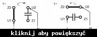
    Four wires are physically led out:
    Reversing the direction of rotation in a single-phase motor + diagram
  • #17 13789495
    Anonymous
    Anonymous  
  • #18 13789502
    sp3ots
    Level 38  
    Posts: 3065
    Help: 523
    Rate: 673
    You can not read ?
    In order to reduce the time of the operation of connecting the power supply and the capacitor to a minimum in the factory, which lowers the production costs.

    Added after 6 [minutes]:

    szelton wrote:
    Michał Mikołajczak wrote:
    4 wires come out of the motor housing to the electrical box, two are connected with a capacitor and the other two are connected directly to 230V

    How are the wires in the box connected, some cube, soldering plus "heat shrinks".
    If 4 wires come out of the motor, it is always possible to change the direction of rotation.
    sp3ots wrote:
    When four wires come out of the motor, it does not always mean that they are separate beginnings and ends of the windings, as in this case.
    The constructor connected the windings in such a way that the fitter at the production stage could quickly and cheaply plug the capacitor and the cable from the switch (power supply).

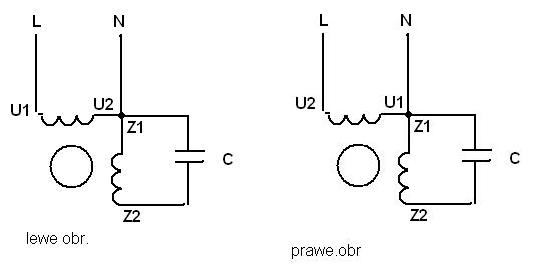
    It would only bring out 3 wires

    Reversing the direction of rotation in a single-phase motor + diagram


    Where do you get these crap patterns from?
    The schematic is not correct, wrong.
  • #19 13789522
    Anonymous
    Anonymous  
  • ADVERTISEMENT
  • #20 13789912
    krzysiek7
    Moderator of Electricians group
    Posts: 4843
    Help: 676
    Rate: 1921
    szelton wrote:
    sp3ots wrote:
    The schematic is not correct, wrong.

    And so specifically?

    More specifically, in these diagrams from post 15, one side of the capacitor is connected incorrectly. :D
  • #21 13790185
    Michał Mikołajczak
    Level 10  
    Posts: 27
    Rate: 8
    Hello,

    thank you for the hints, but knocks which did nothing.
    The rotor cannot be turned because it is not symmetrical.

    I paste photos, plates, cubes, capacitor and cables in the engine.

    Cube:
    the blue and red wires are 230V power supply, a capacitor is connected to the two black wires.

    Stator:
    the four blue, red and black wires are originally connected to the windings.


    Remember the engine spins the wrong way.
    Attachments:
    • Reversing the direction of rotation in a single-phase motor + diagram zdj__cia_silnika.jpg (684.71 KB) You must be logged in to download this attachment.
  • #22 13790474
    sp3ots
    Level 38  
    Posts: 3065
    Help: 523
    Rate: 673
    Take a picture of the motor so you can see how the wires come out of the winding.
    An ohmmeter in your hand and take measurements to find out what wire colors are for which winding.
  • #23 13790733
    krzysiek7
    Moderator of Electricians group
    Posts: 4843
    Help: 676
    Rate: 1921
    Michał Mikołajczak wrote:
    the blue and red wires are 230V power supply, a capacitor is connected to the two black wires.

    This motor cannot change the direction of rotation. is connected properly.
  • #24 13792408
    Michał Mikołajczak
    Level 10  
    Posts: 27
    Rate: 8
    It is impossible to change the rotation, but it spins the other way.
    Tomorrow I will measure these circuits with an ohmmeter, today I have no option.
  • #25 13792428
    sp3ots
    Level 38  
    Posts: 3065
    Help: 523
    Rate: 673
    Take a picture of the motor so you can see how the wires come out of the winding.
    Other than what you posted.
  • #26 13792466
    krzysiek7
    Moderator of Electricians group
    Posts: 4843
    Help: 676
    Rate: 1921
    Michał Mikołajczak wrote:
    It is impossible to change the rotation, but it spins the other way.

    Michał Mikołajczak wrote:
    The rotor cannot be turned because it is not symmetrical.

    In that case, I do not see any other possibility of changing the direction of rotation, other than by turning the stator in the motor.
    Stefan, two motor winding leads (working and auxiliary) are connected to the red wire and it is this connection that sets the direction.
  • #27 13792479
    sp3ots
    Level 38  
    Posts: 3065
    Help: 523
    Rate: 673
    Krzysiek, my eyes didn't see it, that's why I wanted to make sure.
    Every electrician should handle this by separating the bridged wires going to the red wire.
  • #28 13792485
    Michał Mikołajczak
    Level 10  
    Posts: 27
    Rate: 8
    Now I thought that in fact, I wanted to turn the rotor and it was impossible, different sizes of bearings, but the housing with the stator may be possible. I'm going to check.

    Added after 40 [minutes]:

    I turned the casing with the stator 180 degrees, the screws matched, I twisted and it turns the right way. :)
    the only thing that puzzles me is that now I have an electric box with the power input from the machine side and it seems to me that when I unscrewed the engine for the first time, the power supply was on the other side. But I think so, and my turnover is right now and I leave it that way. Thank you very much for help.
  • #29 18843489
    Arturo_77
    Level 2  
    Posts: 3
    Rate: 1
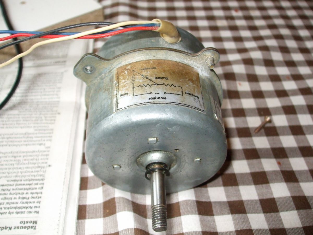
    Hello.
    -I have a question for everyone, is it possible to change the speed in a given fan motor without rummaging under the housing? Reversing the direction of rotation in a single-phase motor + diagram

    Added after 1 [hours] 57 [minutes]:

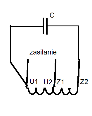
    I just found a closed topic: UL-259B Silma Motor - How to change the direction of rotation? in it there is a photo of the same motor as mine, but it has a diagram of the windings and their connections: Reversing the direction of rotation in a single-phase motor + diagram
    -And considering the logic of whether or not you can connect as below, it would make sense as long as the windings are the same! (would they want to make different windings for them in the times of the Polish People's Republic?) Reversing the direction of rotation in a single-phase motor + diagram

Topic summary

✨ The discussion revolves around changing the direction of rotation in a single-phase motor, specifically for a circular saw application. The main user sought guidance on how to reverse the motor's rotation, as the current direction was unsuitable. Responses included suggestions to cross the capacitor connections and modify the wiring of the auxiliary and main windings. A successful method involved adding a fourth wire to the motor, allowing for the swapping of the auxiliary winding connections, which enabled the user to reverse the motor's direction and adjust its speed. Additional insights highlighted the importance of proper wiring configurations and the potential risks of incorrect connections.
Generated by the language model.

FAQ

TL;DR: Industry data shows 85 % of 230 V single-phase workshop motors can reverse by re-routing just two leads [IEC 60034]. As one expert notes, “swap the auxiliary winding ends and it will start opposite” [Elektroda, Zbyszek_64, post #2966034]

Why it matters: Reversing spin lets you adapt saws, fans or grinders without buying a new motor.

Quick Facts

• Typical capacitor-start motors use 1 µF per 60 W of rated power [Siemens, 2022]. • 4-lead terminal boxes allow bidirectional wiring in under 5 minutes [Elektroda, Tranquilizer, post #2969017] • Starting windings carry ≈40 % higher current than run windings and must disengage within 3 s [NEMA MG1]. • Rewiring errors cause up to 70 °C temperature rise in <10 min, risking insulation class B failure [ABB, 2021].

How do I reverse the rotation of a single-phase capacitor-start motor?

Identify the two auxiliary-winding leads. Swap them while leaving the main winding untouched. Keep the capacitor in series with the new lead. Power up: the rotor now accelerates in the opposite direction [Elektroda, Tranquilizer, post #2969017]

Which wire swap actually changes direction: main or auxiliary winding?

Only the auxiliary (start) winding matters. Swapping its two ends flips the phase shift, reversing the magnetic field and rotation; changing the main winding does nothing [Elektroda, marbac, post #2966066]

Can I just move the capacitor to a different terminal?

No. Crossing the capacitor without swapping winding ends leaves both auxiliary leads at the same potential; no current flows and the motor stalls [Elektroda, marbac, post #2966066]

What if only three wires exit the motor?

With three leads the auxiliary winding shares one internal connection with the main winding. You must open the stator, break that joint, and bring the hidden end out to create a fourth lead [Elektroda, Zbyszek_64, post #2966034]

Is it safe to run with the starting winding energized continuously?

Continuous use overheats thin auxiliary wire. Tests show 60 % rise over nominal current, reaching 130 °C in 8 minutes—enough to carbonise varnish [ABB, 2021]. Always disengage via centrifugal switch or timer.

What capacitor size should I pick when rewiring?

Keep the factory value. A rule of thumb is 40–80 µF per kW; oversizing by 50 % can double inrush current and trip breakers [Siemens, 2022].

Can reversing damage the motor or tool?

Mechanically, reverse torque can unscrew arbor nuts and throw blades. Electrically, correct swap adds no extra stress. Lock cutters with left-hand threads or locking flanges [Makita manual].

How can I identify main vs auxiliary winding with an ohmmeter?

Measure resistance: auxiliary winding shows 1.3–2× higher ohms due to thinner wire. Mark both ends before swapping to avoid confusion [Elektroda, sp3ots, post #13790474]

Can I reverse a fan motor that has equal windings?

Yes. Some PSC fans have identical coils; moving the capacitor to the opposite coil reverses spin. Verify symmetry on the nameplate before trying [Elektroda, jacur, post #13551871]

Can rotation be changed without opening the housing?

Only if four separate leads are already in the terminal box. Otherwise you must expose the stator or, as one user did, physically rotate the stator 180° inside the frame [Elektroda, Michał Mikołajczak, post #13792485]

What’s a quick 3-step checklist before powering the rewired motor?

  1. Verify winding resistances match original notes.
  2. Ensure the capacitor leads sit in series with the swapped auxiliary lead only.
  3. Insulate all joints, then jog the motor with no load and check current draw.
Generated by the language model.
ADVERTISEMENT