logo elektroda
logo elektroda
X
logo elektroda

PNW-57 night vision device. Possibility of making new electronics.

Dolby* 30583 55
ADVERTISEMENT
Treść została przetłumaczona polish » english Zobacz oryginalną wersję tematu
  • #31 18862009
    NiclasLindner
    Level 7  
    Fortunately, silicone is relatively soft. Unfortunately, it breaks into thousands of pieces when removed. But it should be removable.

    The question is, what caused the problem? Never had this problem before!

    At the very beginning, shortly after I purchased it, I operated it on 12 volts for a while. Later I noticed that it is only allowed for 6 volts. But in theory, that doesn't destroy the insulation, right?
    Unfortunately, the current problem also occurs at 6 volts.

    Should I try to remove the old silicone and replace it with a new one? And what exactly is this silicone for insulation called. Here in Germany, I have not yet been able to find a suitable one on the Internet.


    Any ideas how can I measure the high output voltage? I just have a normal multimeter up to 250 volts here.

    Added after 2 [hours] 6 [minutes]:

    Another question (hope I'm not too annoying):

    I also have a PNW-57 power supply nearby. It still works wonderfully and with no problems. Can I use this for the NS-71? Theoretically, the pipes have the same voltage from both units
  • ADVERTISEMENT
  • #32 18862227
    Krzysztof Kamienski
    Level 43  
    @NiclasLindner Does it pierce with or without the lamp connected? Connect the lamp and gradually increase the voltage to obtain a correct picture. I guess that's about 4-5 volts.
    NiclasLindner wrote:
    6 volts. But in theory, that doesn't destroy the insulation, right?
    Why not ??? Voltage increase at the inverter output! Old, cracked silicone!
    NiclasLindner wrote:
    Should I try to remove the old silicone and replace it with a new one? And what exactly is this silicone for insulation called. Here in Germany, I have not yet been able to find a suitable one on the Internet.
    Yes, only before that this arc (spark) could create a carbon path on the PCB. You need to clean it thoroughly.
    Search - "Hochspanung proof silicone gel". They are for sealing cable joints.
  • #33 18862344
    NiclasLindner
    Level 7  
    I measured it once. Lightning came from around 3V at the entrance. This can't be normal.


    But now there is probably one more, much bigger problem.

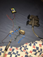
    I was just about to read the input current. Exactly the same test settings as when shooting the movie. This means 6V at the input, optics as a load at the rear. In addition, a thin wire from the minus at the input to the shielding of the high voltage cable. Exactly the same goddamn deal.

    And suddenly ... ... the battery is on ... It burns one of the tracks on the board ... I cut off the power as soon as I could.
    Then I quickly measured it with a multimeter - now it seems that there is a short circuit at the input between positive and negative ...
    I have no idea why, no idea why or especially why, now. Tried this setting dozens of times, nothing happened ...

    That's annoying...


    I don't think I can fix this board anymore. Only a new construction remained.
    Theoretically, it is not difficult to build something like this. With the help of the Internet, I came up with a diagram. My only concern is that high voltage cascades at the 15kV output with too much current could kill me. As a layman, the risk is too great for me without an accurate and proven expert circuit.
  • #34 18862395
    _jta_
    Electronics specialist
    I do not know what the properties of this power supply are - whether it has output voltage stabilization or not. If not, then plugging in a higher voltage battery likely created higher voltage and breakdown - however, usually the breakdown reserve is assumed to be large enough that if the silicone were new it would not have happened. But if it was old, if there were cracks in it, it could have happened - especially cracks, even microscopic ones, are of great importance because they make the electric field locally stronger (just like a blade).

    There are several readily available materials that are good insulators - paraffin, rosin, probably also celluloid and polystyrene. The first two can be melted and poured, besides the paraffin dissolves in gasoline, you need to be careful with rosin, because at a temperature slightly above the melting point, it starts to char and the insulation properties deteriorate, and both must be very clean so that they insulate well and withstand high temperatures. tension; I think celluloid dissolves in acetone, polystyrene also dissolves in something. Probably the easiest way is with paraffin, but it must be clean, bought in a chemical store, and not from a paraffin candle (such a candle usually has impurities and it insulates much worse). But "hochspannung gel" should be better. One of the best insulators, but generally impractical, is sulfur (unfortunately it is corrosive to metals so cannot be used). Teflon is good, but you won't flood the system with Teflon.

    As for PNW-57 - make sure that it will not be overloaded.

    Voltage measurement: basically you need a resistor (or resistor array) that can withstand this voltage. Up to 3kV, I used a few (I don't remember, I think 6) 10M resistors (probably 1/2 W or 1W) connected in series. But be careful with their placement on the board - it must provide good insulation. And you need to determine how many resistors you need not to exceed the permissible voltage (for resistors there is some acceptable voltage, with such a high resistance, the power is "fictitious" - supposedly 3kV at 10M will give 0.9W power, but the 10M 1W resistor cannot be connected to 3kV , it will destroy it - the permissible voltage is specified in the catalog note). And you need to know which output the high voltage is at - it's not like the "voltage" and "ground" outputs are equivalent, "ground" may not have good insulation. Measure the current flowing through these resistors and calculate the voltage.

    Note: it is better not to connect the resistors to a working power supply, but before turning it on - charging the mounting capacities may break the resistor. Can I do so that there are (small) capacitances parallel to the resistors - so that when the voltage suddenly changes, it is transferred evenly to all resistors? But then this voltage change will give a current impulse to the meter, you need to protect it somehow, e.g. by connecting a capacitor (not so small) to it between its terminals.

    In general, the technique of 15kV voltages is difficult - some conductor may discharge into the environment (into the air) because it is too thin.

    Do you have information about the current you need to power this lamp? The current below 1mA should not be felt (it does not matter from what voltage), but touching the capacitor charged to 15kV you will probably feel a lot already at a capacity of e.g. 100pF.
  • #35 18862490
    NiclasLindner
    Level 7  
    Thanks for the detailed answer! I think I can find something like this in insulation materials now. For me personally, chemical paraffin is likely to be the right choice. Just for the sake of ease of processing.

    The information about voltage measurement is also very helpful, it will protect my multimeter from dangerous voltages =)


    But unfortunately I have no idea how much electricity these two tubes are drawing. I only have the name (WEJ-1). Unfortunately, there is absolutely nothing on the internet about it. Here in Germany also there are no real specialists and experts in this field - that's why I am writing here in this forum.

    The lowest possible current would be the right choice for such a self-built circuit - just for safety reasons. But without specifically determining the required amount of current, it is difficult to estimate it.

    I once read on the internet that there are other lamps of this type that use 20mA of current. But it's way too much in my opinion. With 15kV it is 300 W of power!
    I think the current must be much lower with these tubes.
  • ADVERTISEMENT
  • #36 18862501
    AlekZ
    Vacuum tubes specialist
    I quickly put together such a layout as in the pictures. Horizontal deflection transformer from the Soviet TV Junost 402W. Transistor - historic germanium TG70 (ADP670). Diodes - I know the type, some high voltage. I chose the number of duplication levels for the best image. I don't know what condition I have these converters in, so the high voltage value may not be optimal for the better ones. The advantage of the system is that with higher irradiation the accelerating voltage decreases, which to some extent protects the transducers against damage in the case of strong lighting.
  • #37 18862513
    Krzysztof Kamienski
    Level 43  
    @NiclasLindner Due to the principle of operation, these "tubes" consume from almost zero (dark current) to a dozen or so microamperes, i.e. a few watts.
    PNW-57 night vision device. Possibility of making new electronics.

    @AlekZ Turn on the microammeter in the negative multiplier lead and you will know.

    Repeat :!: - Miniature converters are available to power CCFL lamps to illuminate LCD matrices. Such a converter has an output of approx. 3-4 kV AC, with a frequency of approx. 60 kHz. It is enough to add a three-stage duplicator. The whole, with proper assembly, takes up the space of a matchbox. I did it myself once, but the power supply has to be filled with paraffin due to the high voltages.
    https://pl.aliexpress.com/item/32418968693.html
  • ADVERTISEMENT
  • #38 18862532
    AlekZ
    Vacuum tubes specialist
    You don't need to measure. I know from my own experience that microamps will flow there. Anyway, it results from the sensitivity of typical photocathodes (here, probably, polyalkaline is used). After turning off the power of the converter, the image is visible for quite a long time, although - of course - it gets darker and darker.

    There are two possible production sites for WEI 1 transducers in Poland. It could have been a branch of the Industrial Institute of Electronics in Warsaw (ul. Ciołka 8) (then OBREP), ul. Długa 44/50 in Warsaw or the Wrocław branch of PIE (ul. Grabiszyńska) (then OW OBREP).

    The production of night vision transducers was discontinued after 1990. Where did this information come from? When I came to work at ul. In the long one, I found empty folders with titles. There were image sensors there, including cascade ones. This means that several drivers were put together to provide more amplification. Here is the screen of the first one illuminating the photocathode of the second, etc. On Dluga Street I also found an unfinished converter, probably WEI 3 larger than WEI 1. It was military production, hence probably the contents of the files were destroyed and only the covers remained.
    There are also unfinished pickups of another type (they are in one cabinet), which were certainly made at ul. Długa.
    Oral reports of employees say that these converters were previously made at ul. Ciołek.
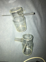
    I got a bag of unfinished converters from Wrocław. It seems, however, that they were some samples. They do not contain a focusing system, which cannot be mounted anymore - both glass panes are already there, and the electrodes of the focusing system cannot be inserted through the side tubes.

    A few days ago I received an unused WEI 1 converter in a box. The production date is August 1971, so the production is still PIE.

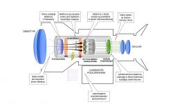
    One more thing: the drawing shown by the user Krzysztof Kamieński does not apply to the WEI 1 converter. This converter is of an older generation and does not have a microchannel plate. As far as I know, it was one of the reasons for the end of the converter production. We have not been able to make such a PCB, and drivers like the WEI 1 have simply become obsolete.
    The diagram of the lamp does not show the focusing electron-optic system and calls it phosphorus phosphor, which is not correct in Polish.
  • #39 18862649
    NiclasLindner
    Level 7  
    I am extremely grateful for your help.

    Also your expertise is very interesting to me! Nowhere else can such "inside information" be obtained! Really fantastic forum and great people!


    I designed some schematic in Eagle. I have combined all your suggestions into one big one.

    My plan was to use the old transformer from the now broken night vision goggle. This is the easiest and most hassle-free way for me. Let's see if it needs to be cast in epoxy if necessary.

    I used Attiny-85 as a clock generator. I don't know yet if it's fast enough. Needs to be replaced with a faster chip if necessary (or I'll build a Royer circuit).

    I can test the high voltage for a night vision device with different multipliers and increase it bit by bit (as said @AlekZ ). So I can look experimental for what's best. Besides, I could save myself on measuring.


    You think it could work that way? So far, I have not found such an approach on the Internet.


    PNW-57 night vision device. Possibility of making new electronics.

    Thanks for the help!!!!
  • #40 18862665
    AlekZ
    Vacuum tubes specialist
    I do not know if it is worth using a microcontroller here. Moreover, it may be sensitive to a relatively strong electric field from the high voltage part.
  • #41 18862876
    _jta_
    Electronics specialist
    The NE555 could be used as a generator of the signal controlling the transistor - it gives a higher output current, it can switch the transistor faster, this will reduce the switching losses.

    When switching off the transistor in the primary winding, high voltage is generated (the leakage inductance plays a role here) - it is advisable to use a circuit that will limit it, so that it does not damage the transistor (and bipolar transistors are more susceptible to damage in such a way, for MOSFETs usually stated what pulse energy they can withstand).

    The secondary winding has a certain capacity which, at a low load current, will be important for the operation of the system. The duty cycle of the inverter is as follows:
    * when the transistor is turned on, the primary winding current increases; in the multiplier system, some diodes are conductive (in a system with one diode, they are not conductive);
    * when the transistor is turned off, a high voltage pulse appears on the collector from the leakage inductance of the transformer; at this time, the primary winding current decreases quickly, and the secondary winding increases rapidly, initially charging its capacity;
    * after charging the capacity of the secondary winding to the appropriate voltage, some diodes (or a diode, because there are versions with one) start to conduct, charging the capacitor (s), and the current begins to decrease (in this cycle, in the version with a multiplier, there are two states in which the diodes conduct - sets of conductive diodes in both states are disjoint);
    * when the current approaches zero, the diodes stop conducting; the charged capacity of the winding contains the energy that remains in the winding system (its inductance and capacitance form a resonant system) - it oscillates;
    * it would be best if within these oscillations the voltage across the collector of the transistor would reach zero (the primary voltage was equal to the supply voltage but had the opposite sign) when the current within these oscillations passes through zero, and at this point the transistor was turned back on (if when the transistor is turned on, the voltage at its collector is zero, so we avoid losses caused by charging the winding capacitance).
  • #42 18862952
    klamocik
    Level 36  
    In the book; Electronics in my car; The malt str110 to 116 air ionizer is described, it is enough to change the tips to get advantages instead of minuses, if they are willing, I will publish photos but the grandchildren have to save me.
  • #43 18864036
    _jta_
    Electronics specialist
    The question is whether it makes sense, because when I was studying, I read Słodowy's book with a friend as a show of ignorance of electronics.
  • #44 18864296
    Krzysztof Kamienski
    Level 43  
    @_jta_ J.Wojciechowski in his "Modern toys" also described a few ionizers and it makes perfect sense. I do not understand this combination and keying here, because building an HV generator with a voltage of 6-9 kV and a current capacity of several microamps is really not an art. he wrote @AlekZ , he even made such a generator ad hoc on the table ..
  • #45 18864722
    _jta_
    Electronics specialist
    Hmm ... I think I mistook Słodowy with Wojciechowski's "Modern Toys". But there is no need to judge by the author, you have to watch a specific project.

    Building a generator (except insulation) is not a big deal; it's harder to get high efficiency, if you do it anyhow, it can go a few% - i.e. a generator will give 16uA 15kV (240mW power), and from a 6V battery it will take a current of about 1A (6W power) ... Maybe I'm exaggerating a bit, but I've already seen a 300V generator in a mass-produced "electric shepherd", which took several times more current from the battery (and thus the batteries for it cost much more) than a generator with the same output parameters, made a little better - and the higher the voltage, the higher they can be loss.
  • #46 18869173
    NiclasLindner
    Level 7  
    Good evening,

    thank you for your constructive feedback and ideas. Now I just built a circuit from your suggestions and simulated it in LTSpice.

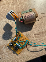
    Today the parts have been delivered. Originally I wanted to etch the board for the low voltage part - but on the bread board I figured it would be faster and easier for something so small.
    It's all over for a few minutes - it even works amazing!

    As a transformer, I took the original transformer from the original high-voltage block. It directly converts 6V to 5kV.

    On the low voltage side, I decided to use a 555-Timer. Together with the transistor and diodes protecting the circuit, the whole thing is even quite small and compact.


    Thank you so much for help!


    With best regards
  • #48 18944358
    dwdasdwadwad
    Level 2  
    Hello. I'm sorry to interrupt but I have a question, I recently bought the NS 71 night vision device and I managed to turn it on, but one eyepiece does not work. Through the first one you can see well (I used the lamp included in the set for observation) and the second nothing. I suspect that a cable could become loose or get tarnished because it would be strange if only one converter burned out and the other was operational. My question is, if this converter burned out, would it be possible, for example, by taking one out of the PNW 57 night vision device, or were other models used in them? Thank you in advance for your answer.
  • #49 18944937
    AlekZ
    Vacuum tubes specialist
    You probably meant not a converter (power supply), but an image converter. Unfortunately, as a vacuum element made of glass, it could, for example, lose its tightness. Such damage to the transducer is irreversible. It then remains to shift from another night vision device.
  • ADVERTISEMENT
  • #50 18945349
    dwdasdwadwad
    Level 2  
    Thanks, and with PNW 57 it would be possible?
  • #51 18968552
    harrymx1
    Level 2  
    Hello, if the topic is still relevant, you can translate the lamp from PNW 57 to NS 71, but they must be worn to the same extent because it affects the quality of observation.
  • #52 20023076
    doofers
    Level 1  
    Hello gentleman.

    I'm from the UK and use Google Translate so sorry for any grammar or formatting problems.

    I recently purchased a PNV 57 kit from eBay and determined that the transformer is powered by a 9V battery but I am not getting the signal from my goggles. Are there any troubleshooting steps I can follow?

    Thanks a lot,

    doof
  • #54 20880714
    Mcrash
    Level 7  

    Hello, let me heat up some cutlets.
    I am looking for a person who would make such a converter for a 9V battery for a fee.
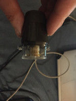
    Can someone explain the idea of a wire between the lamps and the converter? The wire running inside means the power supply, and the braid is the so-called screen mass? I must admit that this is the first time I have encountered such a cable. Please be understanding, I am a beginner when it comes to converters and this type of night vision device.
  • #55 20883787
    harrymx1
    Level 2  
    It is ready for purchase on OLX.
  • #56 20883796
    Mcrash
    Level 7  

    I have already talked to this gentleman and I do not want to say anything more about the correspondence. But I said thank you with that attitude.

Topic summary

The discussion revolves around the PNW-57 night vision device and the feasibility of creating new electronic components, particularly high-voltage converters. Users share insights on the voltage requirements (typically 9kV to 19kV) and suggest various methods for building converters, including using components from plasma balls, CRT TVs, and other DIY solutions. There are requests for circuit diagrams and advice on regulating lamp brightness. Some users report successful modifications and share their experiences with different components, while others seek help for troubleshooting and repairs. The conversation highlights the challenges of working with high voltages and the importance of proper insulation and component selection.
Summary generated by the language model.
ADVERTISEMENT