Elektroda.com
Elektroda.com
X
This content has been translated flag-pl » flag-en View the original version here.
  • Refined desoldering station ZD-915

    Hello.
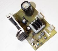
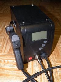
    I would like to present the desoldering station ZD-915 that I have made. The modernization was done already in the first week after buying the device. The condenser, which exploded inside the station, contributed to this. I found that sending back the equipment for warranty repair did not make much sense and I got to work.

    There were a few inconveniences that irritated me in the original layout:
    - continuously working fan;
    - switching the pump motor directly through the miniature switch in the gun and thus - fast burning of its contacts;
    - a one-plate rectifier for supplying this motor;
    - badly soldered wires and often too small cross-section.

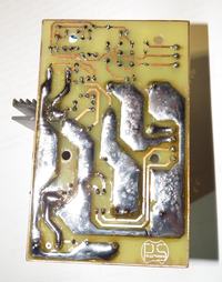
    In my project I eliminated the above-mentioned disadvantages. I used 60N06 transistors to control the heater and the motor, which means there is a considerable power reserve. The radiator to which they are screwed does not even heat up during operation.
    The fan's operation depends on the temperature of the rectifier bridge, which already has a larger radiator than the one in the picture. The fan itself was replaced with a lateral blow.

    The device works without reservations for a year.
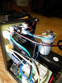
    I think that although the project itself is very simple, it will be useful to someone who wants to change their desoldering bit better. The PCB has been designed to fit into the housings in the casing and does not affect other components of the device. I could not resist :) entire :) case
    Greetings.

    Refined desoldering station ZD-915 Refined desoldering station ZD-915 Refined desoldering station ZD-915 Refined desoldering station ZD-915
    Attachments:

    Cool? Ranking DIY
    About Author
    stepawel
    Level 15  
    Offline 
    stepawel wrote 114 posts with rating 271, helped 8 times. Live in city Częstochowa. Been with us since 2011 year.
  • #2
    krzysztofh
    Level 29  
    During the modification, did you do a pattern of what it was?
    How did you do a new PCB, I mean the program or schematic> pcb or did it without a schematic.
    I'm asking because I have such a station. For now it works and I have not looked at it yet, because there was no need. What about this one-way straightening? Have you used a full bridge and is there too much voltage in the circuit?
    It would be useful to get more information and maybe shallow - preferably in postscripts.
  • #3
    stepawel
    Level 15  
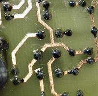
    I made the PCB myself by a thermal transfer, later the tile was covered with rosin.
    PCB will be available as soon as I find :) Will be shared with the list of elements. I usually only do tiles, I have a pattern in my head. PCB is designed in the Altium program, I can upload in .pdf format
    I used a full bridge for the pump motor (he was already in the heater). The engine is adapted to this and what is important is the suction power :)
    greetings
  • #4
    krzysztofh
    Level 29  
    Ok, I will wait. Is there a bone to operate the display on this board? How is it made?
  • #5
    stepawel
    Level 15  
    The display together with the heater control (without the executive system) is on one front plate.
    I've made an executive layout that I think deserved to be changed.
    The PCB project has already been added
    greetings
  • #6
    bodzio667
    Level 18  
    I have a question, what colleague did the compressor use? Is it very loud? If some quinol looks like that to me then I have to admit it's a muddy job. I have a similar compressor in Hot Air PT968. It is so snarling that it drives me crazy. I would gladly exchange it for something silent but I do not have a candidate for it.
  • #7
    stepawel
    Level 15  
    I have not changed the compressor in this device. I admit, his work is very annoying. Often, it was the instinct to make the house revolt. :)
    Some time ago I thought about inserting something quieter there, I had an aquarium air pump on my eye, which should be slightly remade. Unfortunately, I do not implement my plans because of lack of time.
  • #8
    RitterX
    Level 39  
    In total, you have done what you need immediately after the purchase.
    The case of a compressor in a desoldering machine looks a bit hopeless because it has to be a membrane, i.e. one that can cope with high back pressure. The only thing you can do with noise is to start it with a button before desoldering what's going on here.
    In hot air stations, the same compressor is used, connected only by a vacuum tank with desoldering machine. There the noise will be smaller for two reasons. The compressor is two-act or double-skin and the whole station is a piece of metal block that weighs. And if it still has a soldering iron on ordinary trafo, another kilo comes up.
  • #9
    arek59
    Level 29  
    Nice thing with this modification. I have been working for more than 1 year on the original QUICK 706 station and have so far been quiet and nice. Some seem to be walking loudly, according to the instructions should be unscrewed the screw securing the pump for transport.
  • #10
    cooltygrysek
    Conditionally unlocked
    Budego bodzio667 you can use a central compressor with a pneumatic lock with a car, for example, the Audi A4 is small and silent, after that the high suction and discharge power I own in the station after the failure of the original compressor is doing great. Greetings .
  • #11
    krzysztofh
    Level 29  
    And you had the opportunity to compare this car compressor with the original desoldering station from the topic? How is the noise issue?
    The second question is how long it can work, because in cars its work is very short and also switching is not too frequent.
  • #12
    electro
    Level 18  
    I also use the compressor from the central VW lock. The compressor reaches -0.9-1 Bara, so more than the factory, eg weller. As for working time, it is impossible to get used as a dilator. For sure it can run several minutes without interruption, then it starts to heat up.
  • #13
    krzysztofh
    Level 29  
    On All..o they are different, for example with a 3-pin connector and those with a connector probably 8 or more terminals.
    In the car industry, I know little about the issue and hence the question: why do I have so many leads in this compressor?
    I am thinking about buying, because this noise from the desoldering machine also pisses me off.
  • #14
    electro
    Level 18  
    Because in the casing the compressor is also often the whole logic of the central lock
  • #15
    Syntax
    Level 14  
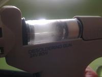
    Do not bother you clogging a tin container? I immediately replaced him with a desoldering machine for a container from Denon SC-7000. All you need to do is cut it down a bit. Now much less often you have to empty it so you work more comfortably.

    stepawel what did you this station and how did you prepare the substrate?
  • #16
    stepawel
    Level 15  
    The station was painted with car spray paint, using a primer paint, also in a spray. Probably there will be reservations that such a thing is not very resistant to scratches, and in my opinion you just have to be careful and respect your devices. :)
  • #17
    krzysztofh
    Level 29  
    Syntax wrote:
    Do not bother you clogging tin container? I immediately replaced him with a desoldering machine for a container from Denon SC-7000. All you need to do is cut it down a bit. Now much less often you have to empty it so you work more comfortably.

    stepawel what did you this station and how did you prepare the substrate?


    Can you give some photo with this container?
    I even created a thread about the clogged container, but few people spoke. In the end I do so that after cleaning I lightly spray the WD40 spring or silicone spray oil. Tin is better off.
    It does not change the fact that you have to clean often.
  • #18
    Syntax
    Level 14  
    Containers from Denon SC-7000 can be bought for about PLN 30 on Renex

    That's how it looked like it was new:

    Refined desoldering station ZD-915

    Refined desoldering station ZD-915 Refined desoldering station ZD-915
  • #19
    stepawel
    Level 15  
    Syntax, can you tell what the tin stops in this filter? Is there something like a polymer sieve?
  • #20
    krzysztofh
    Level 29  
    Exactly. What is the baffle in the center of the sleeve before the sponge or nonwoven filter?
    Does it not block the air flow tin after a few aspirations?
  • #21
    Syntax
    Level 14  
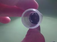
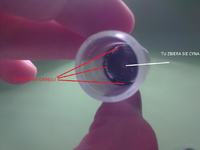
    This partition inside is of the same material as the entire "container". The container is one whole, solid element. There are two filters on the compressor side: one - a thick and thick swab, the other - similar to the one in the cigarette, but I removed it because it did not fit into the ZD-915 pistol. In the image of the new filter, which I placed in the previous post, the second filter - "cigarette" is located on the front of the container (designation FRONT), but it really is mounted behind this filter - a cotton swab. Now the liquid tin falls into the container and stops in the middle of the barrier without blocking the air flow - on the partition near the edge. In the circle there are openings that allow free air flow, even when the container is full.

    Refined desoldering station ZD-915
  • #22
    anilion
    Level 15  
    As a filter in desoldering, steel wool is often used, followed by felt. Steel wool is nothing more than a metal grease cleaner.
  • #23
    Mac3k
    Level 20  
    Hello, does your colleague have an adjustment diagram and a temperature sensor from this gun?
  • #24
    stepawel
    Level 15  
    As far as the regulation system is concerned, I can not copy it as I remember, because there is only a black drop on the tile under which lies the core. What sensor sits in the gun itself, I do not know either. I did not explore this topic as much as I did not intend to change anything in this part.
    Greetings.
  • #25
    Mac3k
    Level 20  
    And maybe I could know at least what voltage is delivered to the sensor? (Could you measure it for me?) Maybe I have a solution because when the soldering iron warms up, the detector reaches about 20 Ohms, something primitive could be something primitive to make it clog and disconnect the heating and set yourself less more some reference point, eg 350 * C permanently.
  • #26
    stepawel
    Level 15  
    Buddy Mac3k, today I started the station to get :) information
    I am introducing a correction to my higher post. There are normal integrated circuits on the controller board, no unpolluted point:
    C8051F310 - the heart of control
    HT1621 - display controller
    HA17358 - operational amplifier
    The rest are small elements.
    Mac3k wrote:
    because when the soldering iron warms up, the detector reaches about 20

    A thermocouple is installed in the desoldering gun. For me, 350 * C is about 35mV.
    I suspect there is no colleague station, only the gun itself. I think that a good solution would be to use a ready-made design of the soldering station and to add a central lock pump there.
  • #27
    Mac3k
    Level 20  
    Well, I do not have a station and I would like to make a central unit, once zd915 were for PLN 180 now it's almost 300 so samoróbka is more profitable the more that has a transformer who will be easily fed. Thank you very much for information! If I manage to finish the project, I will place it on the electrode for another, wanting to have a self-made desoldering machine.

    I still have one problem because I do not have a collar fixing the arrowhead, i.e. I have it, but it is too short because it comes from ZD915-C and the gun is from ZD915 (or vice versa) and I have a problem because I combed half the internet and it can not be bought anywhere, or I am looking for the wrong name.

    My temperature controller plan is as follows. The thermocouple delivers 35mV for a dual operational amplifier where the voltage is amplified 10x to 350mV then again 10x to 3.5V. If it is like a colleague writes that 35mV = 350 ° C, then you can give a voltmeter which will serve as a primitive temperature indicator. Then with this voltage I control the transistor that opens or closes the relay. That is, when the voltage reaches 3.5V, the transistor opens by activating the relay (here a diode signaling heating) thereby opening the power stage transistors through which the heater is fed. The potentiometer can be given to the base of the transistor controlling the relay and thus the primitive temperature control is gained. I have no idea if it will work because I have never made such arrangements. The problem here is probably that the op-amps are not completely linear?
  • #28
    stepawel
    Level 15  
    I suggest the regulator described in the Practical Electronics 07 / 08.2007. This will allow you to build a very decent station. By the way, the project checked. :)
    If the collar is too short, it will probably be faster to fit the heater, than the longer collar. :)
    Greetings.
  • #29
    LewiAdam79
    Level 1  
    Hello.
    Does anyone have a full schematic for the soldering station?
  • #30
    enterrupter
    Level 12  
    Hello, I have the same station and unfortunately there was a failure in it, I do not want to attach at all, I checked the fuse power cords everything is okay, probably something on the transformer PCB was damaged. I would like to convert the circuit board layout to the same layout you made , I have a few questions:
    What kind of transformer did you use to power the entire system, you can give its data?
    What are the inputs on your board described "from the controller" and "to the controller board" or the display driver on the front panel, I have two cubes there, the first one is blue and red, the second yellow and green, where I have them hook up on your tile?
    Greetings.