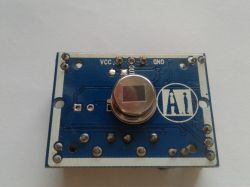
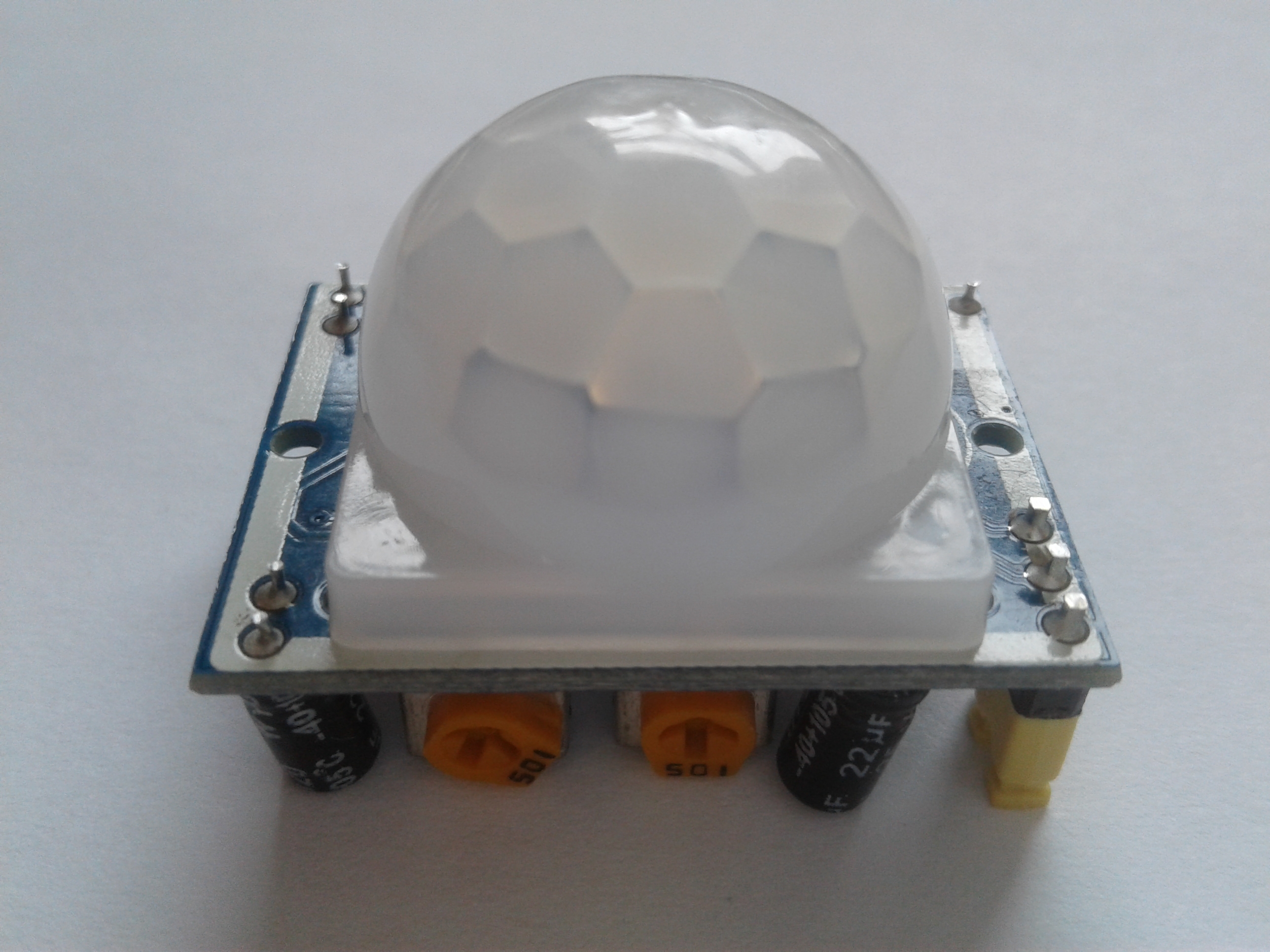
The HC-SR501 sensor is a cheap popular passive PIR motion detector. We can buy it, for example, from Aliexpress for an amount from $ 0.69 with shipment or on Allegro from PLN 6.28 with delivery. This sensor is equipped with the LHi778 IR detector, a Fresnel lens and the BISS0001 integrated circuit that interprets the signal from the LHi778 detector.


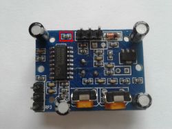
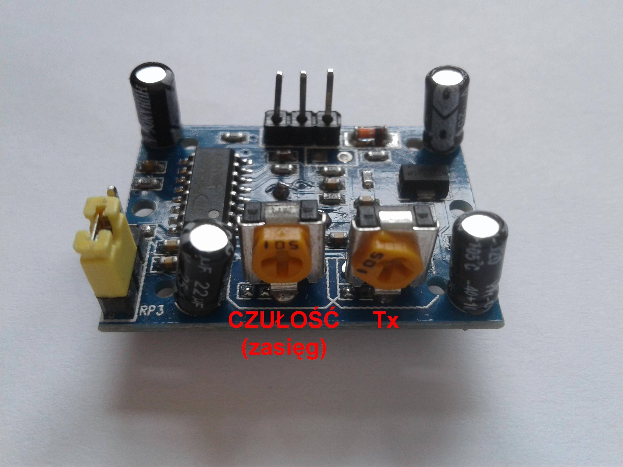
The sensor detects moving objects emitting infrared light, it does not react to the mere movement of objects within its range. When a change in the infrared light intensity is detected, the output changes from low to high. In the operation of this sensor, we can distinguish two times, i.e. Tx time - duration of the high state at the sensor output and Ti time - the time during which motion detection does not work, this time is counted from the end of the Tx time. The Tx time can be adjusted with the potentiometer on the sensor board. Turning to the left decreases the Tx time, turning the potentiometer to the right increases this time. The leftmost position is approx. 3 seconds, the rightmost position is approx. 230 seconds. The producer did not provide for Ti time regulation in this version of the sensor. Here it is approx. 3 seconds. We can change the length of this time by replacing the resistor or capacitor shown in the photo below.
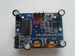
According to the documentation that can be found for the BISS0001 chip, Ti time is the product of the number 29 and the capacitance value and the resistance of the elements indicated in the above photo. On the other hand, the time Tx is the product of the potentiometer value, the number 24576 and the elements from the photo below.
Tx = 24576x (PR1 + Ra) xCa
Ti = 24xRbxCb
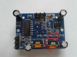
After supplying the power, the sensor gives a high state to the output - after supplying the power, it behaves exactly as if it had detected the object, so after supplying the power to the first detection, wait Tx + Ti time. The sensor output is controlled by the second leg of the BISS0001 chip, which is connected in series with the OUT goldpin through a 1k? resistor. In the photo below you have the resistor marked.
The output works in 3.3V "logic" and has a very low load capacity, which is 10mA according to the documentation, so it is impossible to connect the relay directly to the sensor. If we want to control the relay, it should be done, for example, through a transistor. You can also use a ready-made module that is in Google under the name of eg "1-channel 5V relay module" for this purpose.
The sensor should be supplied with voltage in the range 5-20VDC. As for the current consumed by the sensor, I cannot confirm what Google or the seller gives. It is supposed to be about 65uA in standby mode, and my meter went stupid and shows 20mA or 260uA, and when the object is detected 810uA or 60mA, which has nothing to do with reality, because at the 400mA range it shows me that the LED is powered from 5V through a resistor 1k exceeds the measured value, i.e. over 400mA. It's probably time to say goodbye to this meter.
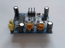
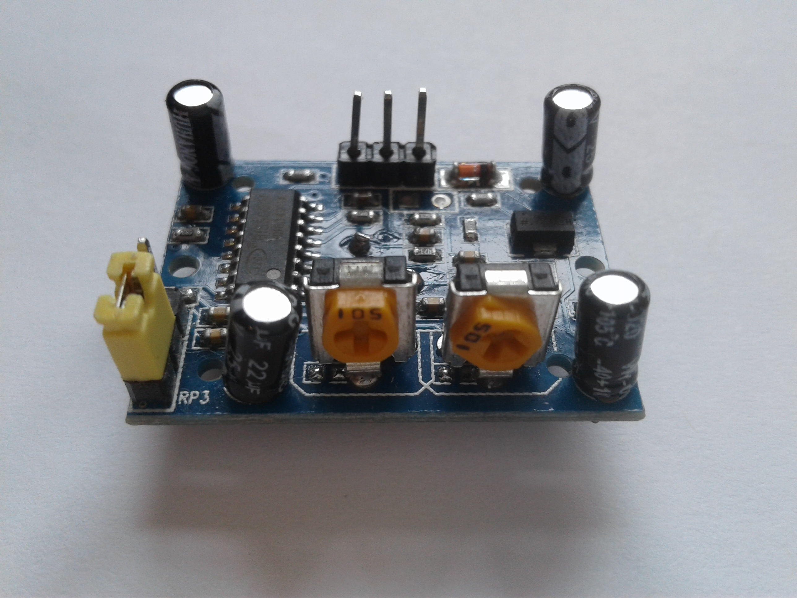
On the PCB, in addition to the 3-pin connector, where we have the power supply and the sensor output, we find a diode working as protection against reverse polarity of the power supply, a stabilizerLDO HT7133-1, two 1M? potentiometers with which we can adjust the Tx time and sensor range in the range from 3.5 to 7m.
The leftmost position of the left potentiometer is the minimum range, the extreme right position is the maximum range.
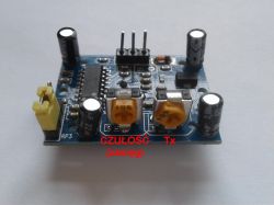
This sensor is not equipped with the signaling of the operating status or the signaling of the object detection. The board also has a 3-pin connector with a jumper to select one of the two operating modes. The choice is made by setting the jumper appropriately, which corresponds to the low L or high H state on pin 1 of the BISS0001 system.
Below is a photo with the items marked.
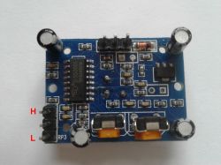
Below are described types of work to pass L or H to the first leg of BISS0001 and their examples for better understanding.
L - after detecting an object, a high state appears at the sensor output, which continues in accordance with the Tx setting. After this time has been counted down, the state changes from high to low and the time Ti counts down, where no detection is performed. After Ti expires, detection starts again and it is possible to redetect the object.
Example (Tx = 9, Ti = 3) - the sensor has detected movement, the sensor output status is high, the Tx time starts to count down. After 4 seconds, an object reappeared within the range of the sensor. After another 5 seconds, the output will change from high to low - time Tx has expired, now the sensor will not respond to the object within 3 seconds - duration Ti. After the 3 seconds have elapsed, detection starts again and the sensor is ready for the next object detection. The sensor output was high for 9 seconds.
H - after detecting an object, a high state appears at the sensor output, which continues in accordance with the Tx setting. Each subsequent detection of an object by the sensor within the Tx countdown time starts the Tx countdown again. If the next movement of the object in the field does not fit within the duration of the Tx time, the high state will change to low and the Ti time will be counted, where detection is not possible.
Example (Tx = 9, Ti = 3) - the sensor has detected movement, the sensor output status is high, the Tx time starts to count down. After 4 seconds, an object reappeared within the range of the sensor. Tx time (9 seconds) is counted down again. Nothing appears in the sensor field, time Tx has expired. The output state is low. Time Ti is counted down where there is no detection. The sensor is ready for the next object detection. The sensor output was high for 13 seconds.
The viewing angle of the sensor is given differently by sellers, some say 100, others 120, and there are also those who write it with an angle of


Comments
I tested two such sensors in conjunction with the Arduino and each time their operation left a lot to be desired. The randomness of switching on was very high, there were also large delays. I tested using... [Read more]
The sensor is very well suited for making a GSM alarm. https://obrazki.elektroda.pl/2152526500_1528560971_thumb.jpeg As a phone, I suggest using Siemens A52 (the option of speed dialing is not blocked... [Read more]
Cool simple design. [Read more]
I used HC-SR501 combined with gsm module, but there was a problem. If I call the GSM module number, the sensor detects movement. I will eliminate this false alarm programmatically, but maybe someone... [Read more]
Maybe someone knows what values you would need to change the resistor and capacitor to lower the Ti time? it would be good, at least by half. [Read more]