logo elektroda
logo elektroda
X
logo elektroda

Tuya Smart WiFi Ceiling PIR Motion Detector PST-HW400B: Pin Configuration & Power Saving Tips

uzverj 2727 10
ADVERTISEMENT
  • #1 20406563
    uzverj
    Level 3  
    Hello!
    Recently I started to dive into the IoT topic and at the moment I'm dealing with:
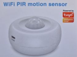
    Name: Tuya Smart WiFi Wireless Ceiling PIR Infrared Movement Motion Detector
    Model: PST-HW400B
    Tuya Smart WiFi Ceiling PIR Motion Detector PST-HW400B: Pin Configuration & Power Saving Tips
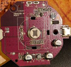
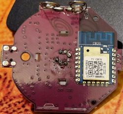
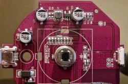
    This is how it looks inside:
    Tuya Smart WiFi Ceiling PIR Motion Detector PST-HW400B: Pin Configuration & Power Saving Tips
    Tuya Smart WiFi Ceiling PIR Motion Detector PST-HW400B: Pin Configuration & Power Saving Tips

    Using "tuya-cloudcutter" I was able to install "OpenBK7231N_UG_1.15.365.bin" firmware to it by Wi-Fi without soldering and UART.
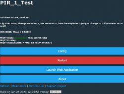
    After that I updated to version 1.15.389 through OTA using WebApplication and connected to MQTT broker. It seems that this device is without TuyaMCU.
    Tuya Smart WiFi Ceiling PIR Motion Detector PST-HW400B: Pin Configuration & Power Saving Tips

    My question is how can I figure out what pins are used for?

    I'm going to use this device as PIR with external power supply unit. But it would be good to understand how to configure "deep power saving" and battery level on this device.
  • ADVERTISEMENT
  • #2 20406632
    p.kaczmarek2
    Moderator Smart Home
    Hello, please first narrow down the possible pin candidates by looking at the PCB tracks and/or by checking with multimeter (there are traces going to PIR sensor, you can check them with multimeter if you scrap the soldermask from the board, but do not of course cut the tracks accidentally).
    Then, in openbeken, you can set pin candidates to, for example, digitalInput (dInput) or maybe to dInput_noPullUp (I don't know at the moment), set separate channel for each pin candidate and try to trigger the sensor and observe which channel changes.
    Helpful post? Buy me a coffee.
  • #3 20413225
    uzverj
    Level 3  
    It is not so easy a task to track the connection between pins. Some of the traces are located under elements. Okay let's moving forward step by step.
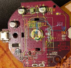
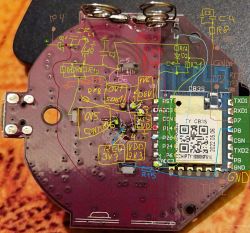
    At the moment I was able to trace some connections and made some voltage measurements. This is a draft and if something is not clear please ask the question.

    PIR BS612 module - voltage measurements - connection
    1(SENS) - 0v1
    2(OEN) - 1v6
    3(VSS) - 0 (GND)
    4(VDD) - 3v3
    5(REL) - 3v3 -> R15 -> CB3S (pin 13) P8
    6(ONTIME) - 0v5

    My electronic skills are not so good. This is what I was able to trace and show on the PCB.
    Up side
    Tuya Smart WiFi Ceiling PIR Motion Detector PST-HW400B: Pin Configuration & Power Saving Tips

    Down side
    Tuya Smart WiFi Ceiling PIR Motion Detector PST-HW400B: Pin Configuration & Power Saving Tips
  • ADVERTISEMENT
  • #4 20415760
    uzverj
    Level 3  
    Is this enough to start some experiments with PIN configuration?
    At the moment I don't understand what PIN I should configure with what parameters. Can you suggest some options? It will be good if they will be with real examples. And where I should see the changes?
  • ADVERTISEMENT
  • #5 20415827
    p.kaczmarek2
    Moderator Smart Home
    Very good reverse engineering. My only question would be, why do you have ADC3 twice?

    Hmm CB3S docs clearly shows which pin is which Px role.

    If you think that, for example, P26 is a input of PIR sensor, they you can try setting P26 role to "dInput" and then watch channel 0 value on Gui (it should show up), is it changing to 1 if you try to trigger sensor?

    about PIR sensor:
    Quote:

    This PIR sensor itself is pretty straightforward and works out of the box. Simply apply power 5V – 12V and ground. The sensor output goes HIGH when motion is detected and goes LOW when idle (no motion detected).
    Helpful post? Buy me a coffee.
  • ADVERTISEMENT
  • #6 20416226
    uzverj
    Level 3  
    Regarding PIR, as I understand correctly it is not so simple it is working on 3V. Please check the link.
    https://evelta.com/pyroelectric-infrared-sensor-6pin-3v/

    According to my investigations PIR pin 5(REL) connected to CB3S pin 13 (with mark P8) through resistor R15.
    I made measurements and I see 3.3v on PIR pin 5 (REL) and CB3S pin P8 constantly.
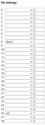
    Unfortunately I can't receive any output from the PIR. I was trying to configure "dinput", "dinput_n", "dInput_noPullUp" and "dInput_noPullUp_n" in configurator for field P8.

    I was able to light the diode assigning LED_n to P26.
  • #7 20416260
    p.kaczmarek2
    Moderator Smart Home
    I don't know this specific sensor, but there is a following description:
    Quote:

    On the digital intelligent integrated circuit chip, the digital intelligent integrated circuit converts the signal into ADC digital signal, there is a timed REL level output when the PIR signal exceeds the selected digital threshold. The OEN enable terminal enables the REL output or automatic control by the light sensor. Sensitivity and time parameters The number is set by a voltage divider resistor. All signal processing is done on-chip.

    so maybe it's worth trying to set ADC role one one of the connected pins? Remember to set ADC channel to something else than dInput channel if you have one, because in this case two input pins would try writing to the same channel and you'd see seemingly random changes on gui.
    Helpful post? Buy me a coffee.
  • #8 20420507
    uzverj
    Level 3  
    Thanks for your assistance!
    Now I know how this PIR PIN's should be configured to send information about motion detection.
    Tuya Smart WiFi Ceiling PIR Motion Detector PST-HW400B: Pin Configuration & Power Saving Tips

    It took some time, because of PIR behavior. When PIR reacts to motion it changes signal on Channel1 from 0 to 1 and holds it for 30 seconds approximately.
    According to my understanding to make this time shorter I need to cut off resistor R10 and connect PIR PIN 6 (ONTIME) to GND. Then ONTIME should be 2 seconds. Can you comment this?

    I added the PIR to my Home Assistant through "Home Assistant discovery" and it appeared in HA as a device with two options "Sensor" and "Control". When I click on "Control" PIR receives the command and switches Channel1 from 0 to 1. Is it possible to block this on PIR side?

    With original firmware PIR is able to show Battery level. Do you have any suggestions how Battery level can be configured in OpenBeken firmware?
  • #9 20425368
    uzverj
    Level 3  
    It is enough to disconnect power from resistor R10 and now ONTIME is 2 seconds. This means that when motion is finished value for Channel1 will be set back to 0 in 2 seconds instead of 30 seconds.

    Tuya Smart WiFi Ceiling PIR Motion Detector PST-HW400B: Pin Configuration & Power Saving Tips
  • #10 21158243
    AntonShylo
    Level 1  
    >>20425368 .
    Thanks a lot! It really works better and is quicker to respond.

    Has anyone encountered this phenomenon where the sensor starts blinking the red LED for about 15-20 seconds and doesn't respond to anything, and then continues to work normally?
  • #11 21319851
    Marko121
    Level 17  
    Hello.
    I have programmed myself such a wifi pir detector with the file OpenBK7231M_QIO_1.17.606 BK7231Flasher programming was successful, but how can I now access this detector and set the ports ? (I do not have a home assistant) Is it possible to connect directly with the phone and set up these inputs, how do I do this?
    Second question, will a detector with this software only work with home assistant or with any other software?

    Regards

Topic summary

The discussion revolves around the Tuya Smart WiFi Ceiling PIR Motion Detector (Model PST-HW400B) and its pin configuration for optimal functionality. The user successfully installed custom firmware (OpenBK7231N) and connected the device to an MQTT broker. They sought assistance in identifying pin functions and configuring the device for deep power saving. Various voltage measurements were shared, revealing connections to the PIR sensor. Suggestions included using a multimeter to trace connections and configuring pins as digital inputs. The user successfully configured the PIR to detect motion, adjusting the ONTIME parameter for quicker response. They also inquired about integrating battery level monitoring in the OpenBeken firmware and reported issues with the sensor's LED behavior.
Summary generated by the language model.
ADVERTISEMENT