Assumption
Half bridge LC resonant with parallel load to C topology. I don't know why but we can find information about it as "parallel resonant converter" that I think is not a true (where is parallel resonant here?)
Supply voltage = 230 AC ≈ 325DC
lowest frequncy = 100kHz
higest current on primary winding = 800mA
output voltage ≈ up to 15kV
output current = few mA
Core assumption
Core:
https://feryster.pl/etd49
bobbin:
https://feryster.pl/assets/nowa/karkasy/pdf/etd/ETD49-K-H-20P-5S.pdf
$$A_e = 211cm^2$$$$A_w = 273 cm^2$$$$l_e = 114 mm$$$$u (permability) = 1900*0,000001256637 = 0,00238761 [ \frac{V*s}{A*m} ]$$$$H_{max} = 40 \frac{A}{m} $$$$J (current \ density) = 4.5\frac{A}{mm^2}$$$$k (filling \ factor) = 0.3 \ \ \ using \ TIW \ and \ multi \ section \ bobbin$$$$k (coupling \ factor) = 0.6$$
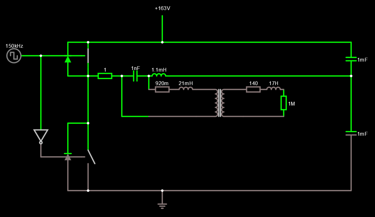
Ideal components model for this topology. We can see it's work as current source:
http://tinyurl.com/y4up4hmj
Idea of schematic for real converter:
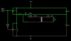
Fig 1. idea schematic 1
In ideal model this will work fine, but we have big leakage inductance on transformator. While I assume hight frequency (minimum 100kHz) voltage drop on leakage inductance will be significant.
For calculation we need assume what shape and amplitude have voltage on primary winding. Highest value of volt-second is in resonant state, then it is sinus shape with amplitude depended with LC quality factor. If we assume some quality factor limits (e.g. by driver from voltage or/and current measure) let's say Q=6, then we can caltulate highest amplitude of voltage on primary winding.
Amplitude of square wave is 162.5V (half of 325V), then 1st harmonic is:
$$1st \ harmonic \ amplitude = \frac{4*162.5}{\pi} = 206.895V$$
and RMS:
$$RMS \ 1st \ harmonic = \frac{206.895}{\sqrt{2}} = 145.298V$$
With Q factor equal 6 we got approximately 877.79V RMS value of voltage on primary winding.
Now we can check if chosen core is enough.
Ap we can caltulate or get from documentation. For chosen core Ap = 57603mm^4
We calculate now how much we need Ap for fulfill assumption:
$$A_P = \frac{V_1*D_{on}*2*I_{1rms}}{f_s*\Delta B *J*k(filling \ factor)}$$
Don is duty cycle and we work with half bridge. This value is 0.5.
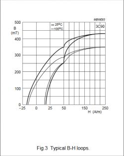
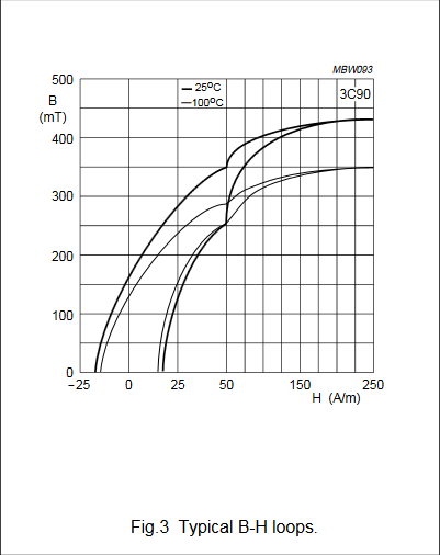
Delta B is equal to H * u(permability). From core material documentation we can choose value of B field and permability.
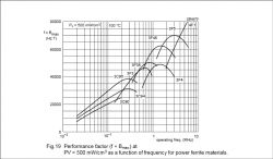
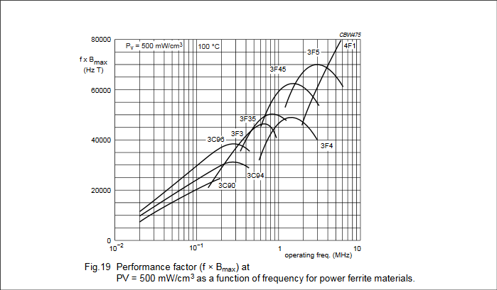
However, we can also find magnetic loss plot. On this plot we can read value of Bmax*f vs frequency. We can use Bmax*f value for assumed 100kHz and multiple it by 2
(or not?) (because we will work with symmetric +Bmax and -Bmax).
I1rms is assumed maximum rms current flow by primary winding. let's assume 800mA.
I will use in calculation value of H field:
$$A_P = \frac{877.79*0.5*2*0.8}{100000*40*0,00238761*4.5*1000000*0.3} = 54466mm^4$$
We check Ap and it's look well but on edge.
Calculation primary winding:
$$n_1 = \frac{V_1 * D_{on}}{H*u*A_e} = \frac{877.79*0.5}{40*0,00238761*211} = 108,9 \approx 109$$
I want have V2 = 15kV on second side then n2 winding:
$$n_2 = \frac {\frac{V_2*n_1}{V_1}}{k(coupling \ factor)} = \frac {\frac{15000*109}{877.79}}{0.6} = 3101,51672 \approx 3101$$
I don't really know how correct estimate k coupling factor. This is important factor, but hard for me to estimate.
But lets assume this 0.6 k coupling factor
We can get from core documentation AL parameter, so that we can calculate primary and secondary inductance:
$$L_p = {n_1}^2 * AL \approx 55.32mH$$$$L_s = {n_2}^2 * AL \approx 44.87mH$$
if k coupling factor is 0.6 that mean leakage inductance:
$$L_{lp} = L_p * (1-k) = 55.32* (1-0.6) = 22.13mH$$$$L_{ls} \approx L_s * (1-k) = 44.87* (1-0.6) \approx 17.95H$$
For simplify schematic we will reflect secondary leakage inductance to primary side:
$$L_{ls'} = \frac{n_1}{n_2}*L_{ls} \approx 22.13mH$$
then we got leakage inductance seen from primary side:
L = L_{lp'} + L_{ls} = 22.13 + 22.13 = 44.26mH
Now we need chose L and C for resonant tank. Let's say L = 20mH and C = 127pF.
Now I will use formulas from book "układy rezonansowe w energoelektronice" by authorship Tadeusz Citko, Henryk Tunia, Bolesław Winiarski.
$$R_0 = 50kΩ$$$$V_0 = \frac{1}{\sqrt{LC}} = 627455.81$$$$Z_0 = \sqrt{\frac{L}{C}} = 12549.12$$$$f_0 = \frac{V_0}{2*Π} = 99865kHz$$$$Q_0 = \frac{R_0}{Z_0}= 4$$
current amplitude at 100kHz:
$$I_{om} = \frac{2*U_d}{Π*Z_0}* \frac{1}{\sqrt{{Q_0}^2* (1 - (\frac{ω}{V_0})^2)^2 + (\frac{ω}{V_0})^2}} = 8.23mA$$
Maximum amplitude of current on load accure at frequency:
$$f_r = f_0*\sqrt{1 - \frac{1}{2*{Q_0}^2}} = 96669Hz$$
and we can calculate this carrent by equation
$$I_{omMAX} = \frac{2*U_d}{Π*Z_0}*\frac{1}{\sqrt{1 - \frac{1}{4*{Q_0}^2}}} =8.24mA$$
There is something that I miss or I understand in wrong way?

Comments