Last December I acquired a second-hand printer, or rather a 3D printer substitute, the Anet A8. Without going into too much detail, the manufacturer's use of what was probably polycarbonate as a frame material very quickly became apparent. I tried to save the cracked structure with aluminium reinforcements, but it quickly cracked in other places. With the rest of my strength, the printer spit out the parts needed to assemble a stiffer frame based on the 2040 structural profiles. At the beginning, the project assumed only a stiffer, more robust frame, but I quickly changed my mind and got rid of the original motherboard (Atmega 1284 + 4x A4988) in favour of the cheap and popular SKR Mini E3 v1.2. The printer is still in the testing and modification stage, it is still getting new "ficks"
 1. Power supply and cabling
 12v240..jpg (30.25 kB)You must be logged in to download this attachment.
Nothing special, an ordinary Chinese 12V 20A power supply, I have improved and refreshed this and that in it:
- slightly larger filtering electrolytes at the input (470u instead of 330u),
- branded filter capacitors on the output, by the way higher capacitance (3x 3300µF instead of 3x2200µF) and of course low esr,
- bold current paths,
 12v240..jpg (29.58 kB)You must be logged in to download this attachment.
- heat sink on the rectifier bridge at the input,
- new thermal conductive paste on power transistors and double Schottky diode,
- 3 layers of heat shrink sleeve on the glass fuse.
"In the days to come" I intend to add a board with a simple transformerless power supply and optocoupler, informing the microcontroller of the mains voltage loss even before the capacitors in the power supply are discharged. I want to achieve more or less the same print resumption after a power failure as in the Prusa i3 MK3s - recording the head position at the time of the power failure + raising the head in Z or moving it off the printed part. I will probably still have to increase the capacitance in the power supply, but it's probably worth it
The power supply to the board ran with LGy 2.5mm2 wires, as did the power supply to the table heater control module. The rest of the wires from the limiters, fans, sensors or motors are also LGy, but 0.5 mm2.
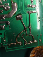
2. Motherboard
 plyta.jpg (160.6 kB)You must be logged in to download this attachment.
 2
BTT SKR Mini E3 V1.2 - 4 TMC2209 stepper motor drivers on board, operating in UART mode; STM32F103RCT6 microcontroller - 32 bit, 72 MHz. Theoretically the TMC2209s allow collision detection, but for now my modest knowledge does not allow me to use this feature at print time, I have instead done some other tests and am able to use this at least for endless basing in the xy axes and synchronising the Z axis motors. For the time being, however, I am sticking with the classic limit switches so as not to add further uncertainties and problems.
3. Stepper motors
Here I used all the original motors from the Anet A8 printer, i.e. 42shdc3025-24b - 0.9A per phase, 0.4 Nm holding torque, 1.8 degrees/step. I only changed the bearings (625) to a slightly better quality (SKF, additionally with 2RS sealing instead of ZZ), and repositioned the flat springs in the Z-axis motors so they wouldn't have a chance to affect the print quality. Previously, the weight of the entire X-Z beam rested on these two flat springs, now I have placed them between the top cover of the motor and the bearing.
4. Linear guides and bearings
The original guides were useless, made of a mysterious
masolite and covered, for no apparent reason, with decorative chrome. I replaced them with normal fi8 line shafts, and in choosing bearings fell to Misumi.
5. Trapezoidal bolts and nuts
Surprisingly the original trapezoidal bolts turned out not to be of such tragic quality as the guides, so I decided to use them. Initially I used brass ones with a spring and backlash canceling counter-nut, but I ended up using iglidur l150 printed backlash-free nuts. They have worked several hundred hours and so far show no signs of wear. The engine-trapezoidal bolt couplings are bolted self-centring couplings.
Link
6. Display
Anet's 2004 display with five buttons and lcd remains, with minor modifications (powering the analogue button design with 3.3V instead of 5V, slightly differently arranged pins in the plugs) - I won't elaborate here, just provide a link to a video explaining all the modifications
7. Frame
 rama.jpg (186.54 kB)You must be logged in to download this attachment.
 6
Typical Anet AM8 project
pheneeny
https://www.thingiverse.com/thing:2263216/files
Pictured still with a Prusa i3 MK2S extruder and a different fan.
8. E, X, Z axes
 exz.jpg (247.31 kB)You must be logged in to download this attachment.
Z-axis transplanted from Prusa i3 MK3, motor and Z-guide mounts modelled on AM8, I only changed the distance from the trapezoidal screw axis to the guide axis. Similarly, the X-axis carriage and the extruder, all 'plucked' from the Prusa i3 MK3. I thought it worthwhile to use the refined and tested design of these components. The head is a Chinese clone of the J-Head E3D V6, with an all-metal (stainless steel) connector and, in addition, a silicone heat block cover. The print is cooled by a Sunon MF50151V1-B00U-A99,
 sunon.jpg (182.01 kB)You must be logged in to download this attachment.
and the head radiator is an AAB Super Silent Fan 4 (not visible in the photos). Print cooling tunnel made of ABS, the rest of the components PET-G. The extruder has a 623 bearing (pressure) and an MK8 knurl (drive) instead of the BMG double knurl. Instead of a P.I.N.D.A. levelling sensor, I used a regular 8 mm diameter inductive sensor.
9. Y axis
So far, an "anet" MK3 12V table, rigidly bolted to the Y bogie. I've replaced the power and thermistor wires with silicone ones and stuffed them in nylon braid. They are temporarily caught with a 'tritite' to one of the table screws and soldered to the pads without any connectors. In addition, I used an off-the-shelf external nmos transistor module to control the heater, in order to lighten the load on the board and minimise the chance of damaging the transistor on it. The printing surface is temporarily Coropad 202x202 mm and ultimately 0.5 mm H17 stainless steel sheet.
10. Firmware
Here, perhaps unsurprisingly, the latest Marlin 2.0.5.4.
I changed a little, of course, besides configuring "everything" I increased the maximum head temperature to 300 degrees, I checked, it is able to reach that much and print with that temperature.
I think that's it, every now and then I will add updates with a description of the modifications made.
I invite you to (constructive) criticism


Comments
That goes for those say "newer" kits, those silver plated goownolite guides are indeed a mega failure. In my case I replaced them with M8 linear fighters from CNC Centrum with bearings also from this shop,... [Read more]
But for at least something embracing to an electronics hobbyist, in the hands of an uninformed user it can be quite a hazard (table plug contacts, the aforementioned crappy fuse socket, no thermal protection,... [Read more]
With such a frame, it doesn't print accurately. How many steps does the extruder have? If it has no gear ratio it's also a tragedy, it gives 25mm per revolution. You didn't write anything about the belts... [Read more]
Chinese no-name belts with 2GT profile, fibreglass reinforced, I find them sufficient. The MK8 fi7.3 (7.25) gives 22.7 mm per revolution, the motor 200 steps/rev, BUT it doesn't do full steps - 1/256 microstep.... [Read more]
https://obrazki.elektroda.pl/1645019400_1600114491_thumb.jpg It would be useful to print out the display panel, but that's after changing to one with an encoder, trim the line shafts, add a "gate"... [Read more]