A self-contained 7-segment colour display module uses WS2812B RGB LEDs, a custom Eagle PCB, and a 3D-printed housing.
Each digit is built as a 5 cm by 5 cm tile, with a Blender-designed overlay that shapes the segments and diffuses light.
The display is driven from a single data pin with the Adafruit_NeoPixel library, and the sample Arduino code handles digit division and countdowns.
The prototype worked with an Arduino UNO and Nano, showed readable segments and colour tests, and three modules were chained for a temperature display.
Main drawbacks were incorrect connector spacing, light leakage from the printed sides, and a need for better diffusion and possibly more LEDs for brightness.
Generated by the language model.
Hello my dears I would like to present here my attempts to make a self-contained 7-segment display based on WS2812B colour LEDs, my own PCB and a case printed on a 3D printer.
The display shown here I will test with an Arduino and give full operating codes for download.
Heart of the display - WS2812B LEDs The display is based on WS2812B 'smart' coloured LEDs, a large number of which can be controlled by a single pin. These diodes only require a power supply (5V and ground) and one signal, they are connected like this:
(in the case of long wires, it is still worth giving a resistor on the data line before connecting to the microcontroller)
Of course, controlling them requires a suitable protocol.
I wrote more about them in the topic PIC18F45K50 as WS2812 LED strip driver , here:
https://www.elektroda.pl/rtvforum/topic3590731.html
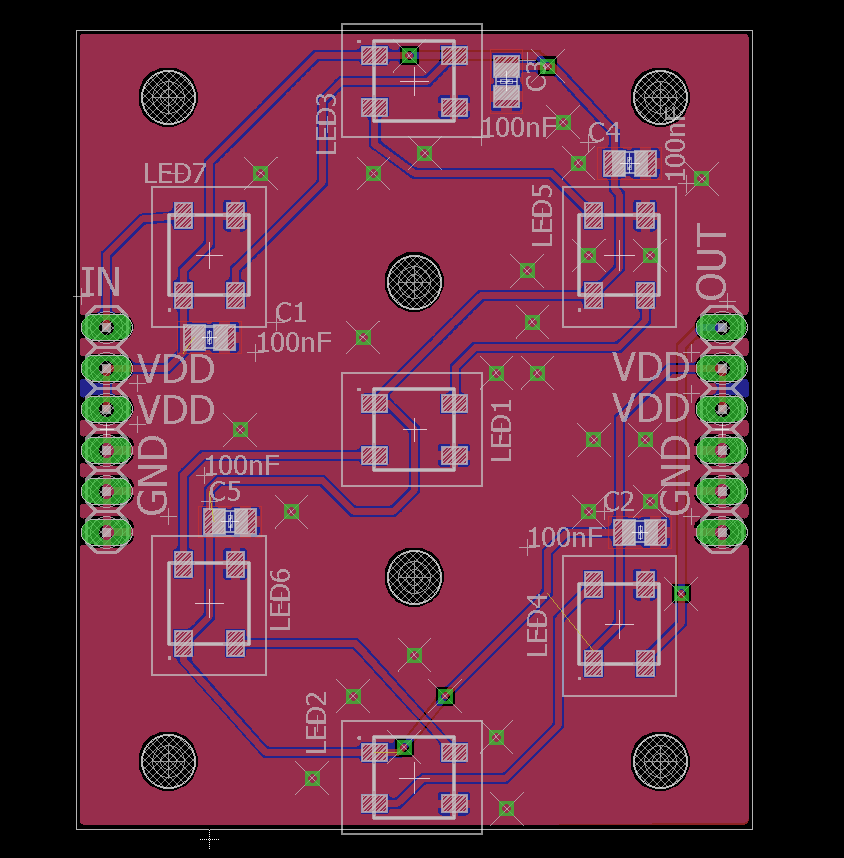
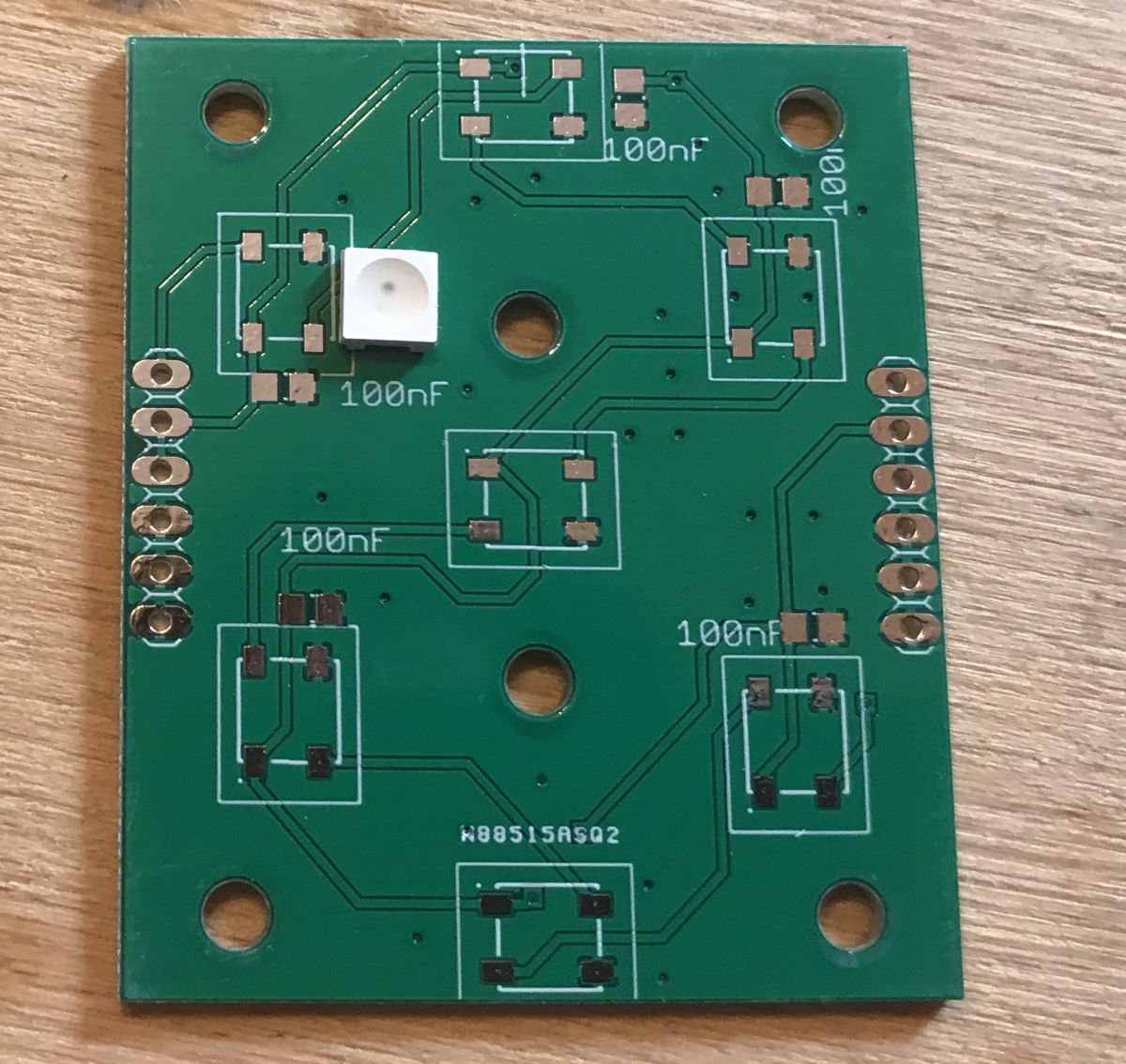
Board design I started the design of my own display by planning the board. For this I used the free version of Eagle software.
The tile represents a single digit. The digits can be connected together and have more digits (controlled by a single pin anyway) by using the WS2812B.
I have tried to make the whole thing no larger than 5cm by 5cm, as most PCB shops will accept panels up to 10cm by 10cm at a cheaper price, which will allow me to order more of my tiles (4 tiles per panel) more cheaply in the future.
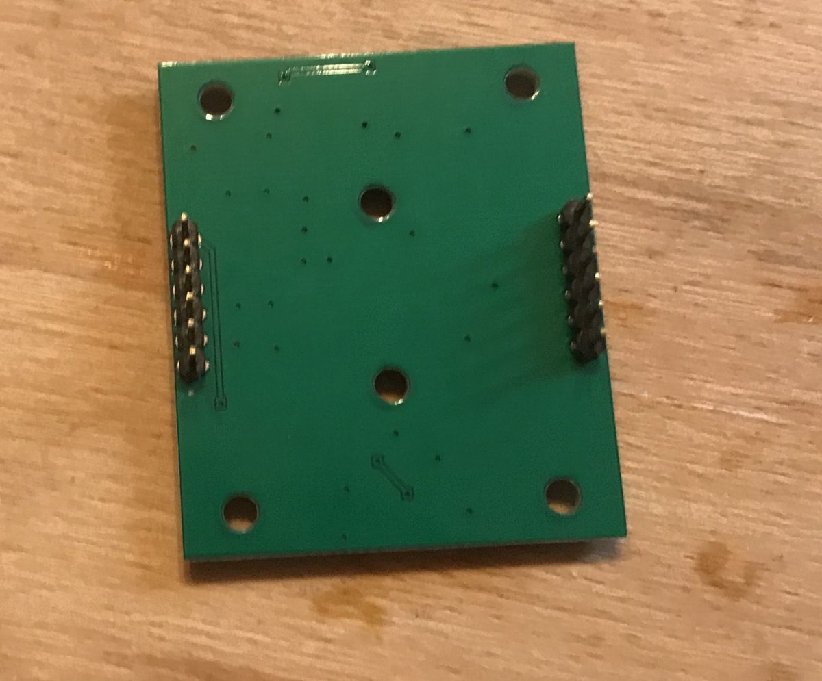
There is a small error on the board - the distance from the goldpin connectors on the right and left side to the edge of the board is a bit too large, making it impossible to connect the two boards together with jumpers alone. This is necessarily to be corrected in the future.
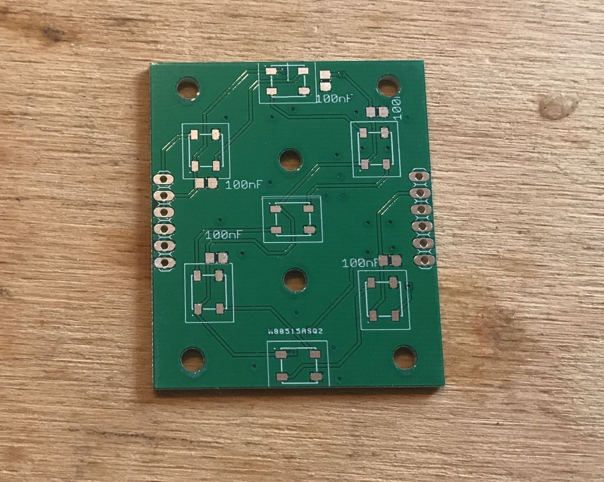
I exported the boards to Gerbers and had the board shop make them (as a start without a panel - this is the first version).
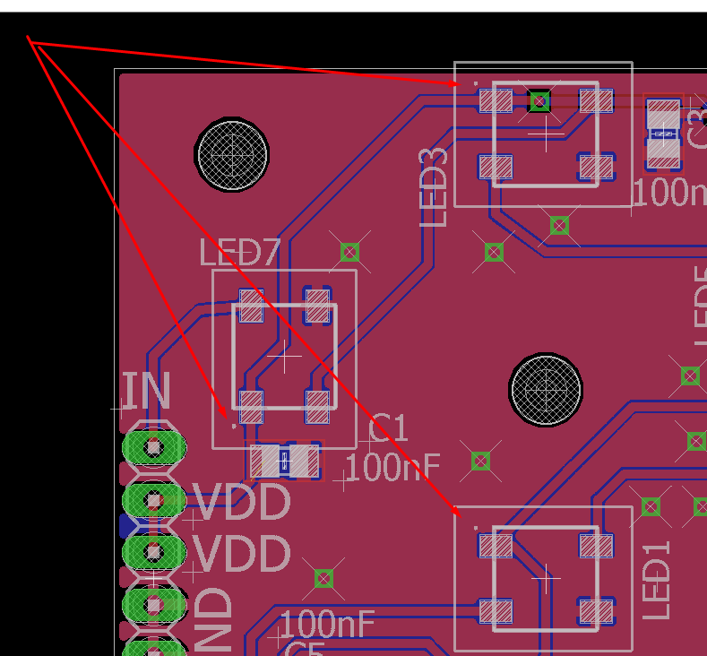
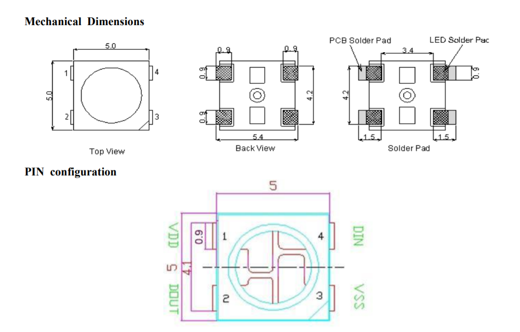
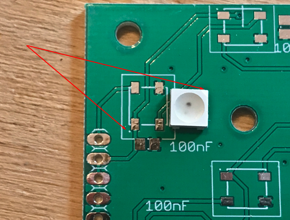
Soldering the board Even before soldering the board itself, it is worth stressing one very important thing. The WS2812B diodes should, of course, be soldered in the correct orientation - you can't flip the diode and confuse the pins. You need to pay attention to the markings. On my board (made in Eagle), the first pin is marked with a dot:
The WS2812B itself, on the other hand, has a truncated corner in place.... third pin: That is, the dot is supposed to be on the opposite side (diagonally) to the truncated pin on the WS2812B.
Armed with this knowledge we can start soldering:
Appropriately positioned element:
Soldered:
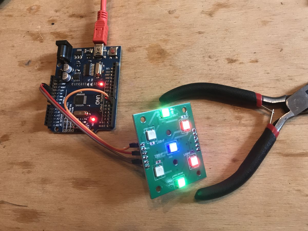
First test with Arduino UNO and "Adafruit Neopixel Library":
In the process of soldering (I soldered the whole thing with the cheapest soldering iron from china):
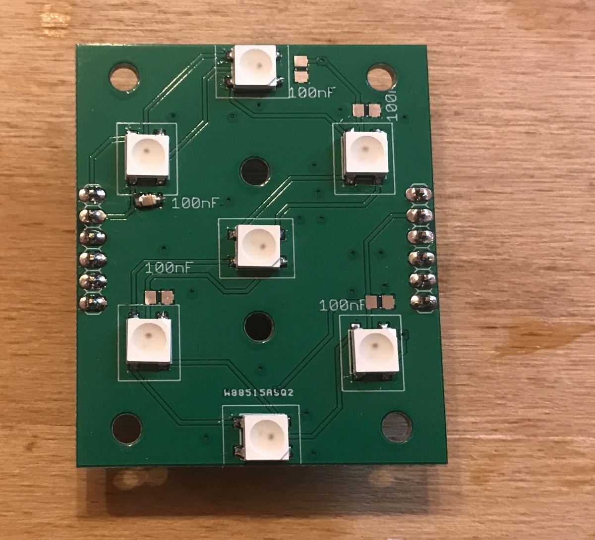
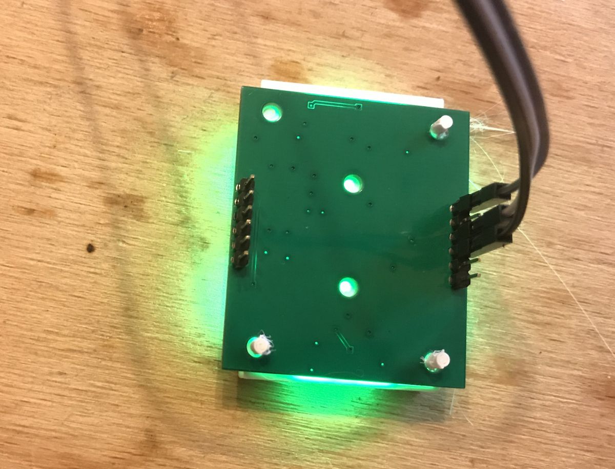
Finished module:
First digit test:
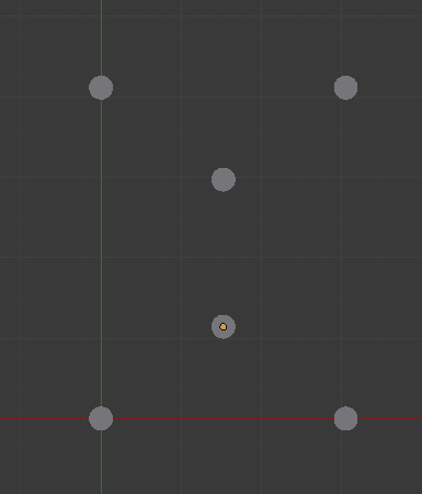
The 3D design of the display I then started Blender and took to designing a 3D overlay for the diode board to shape the digit parts. I started by transferring the holes from the PCB (I will use these for assembly):
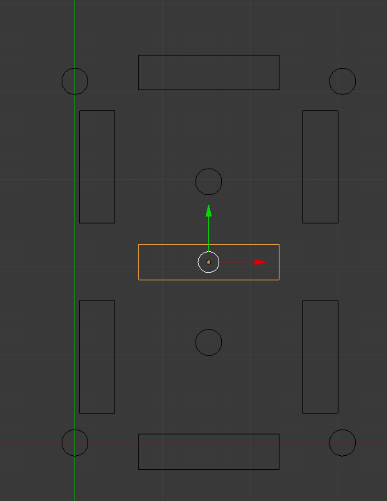
I then decided on the size of the segments and applied their initial shape:
Then I refined their shape and prepared the final element (in Blender I used the Boolean operation to cut the segments out of the cube):
This is how I gave the whole thing a third dimension (the central two cylinders are the holes; the four on the corners are the tabs):
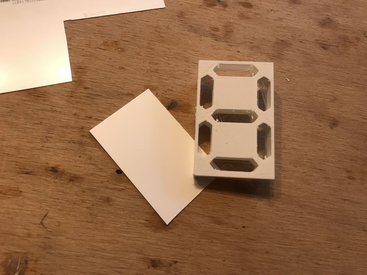
Display 3D printing and fitting The component came out right the first time. On the board it looked like this:
But that's not the end of the story, because you still need to make some sort of overlay that diffuses the light at least a little and gives the effect of whole segments (rather than individual LEDs) shining through.
I wasn't sure what was best to use for this, so I used one of the layers from the inside of an old LCD matrix (whose teardown I described recently in the 'device interiors' section). I chose the layer that gives the best effect, white/milky:
I applied it to the printed part using droplet/superglue, as I was no longer planning to change it.
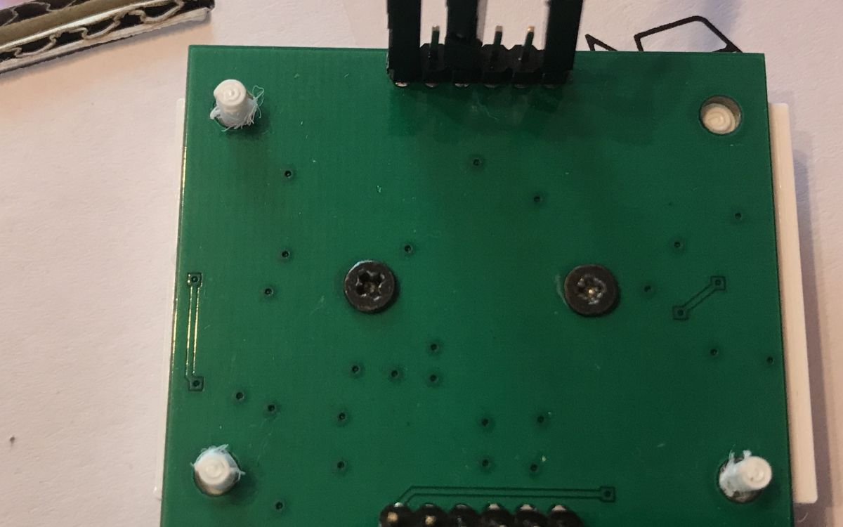
I attached the printed component to the PCB using laptop screws:
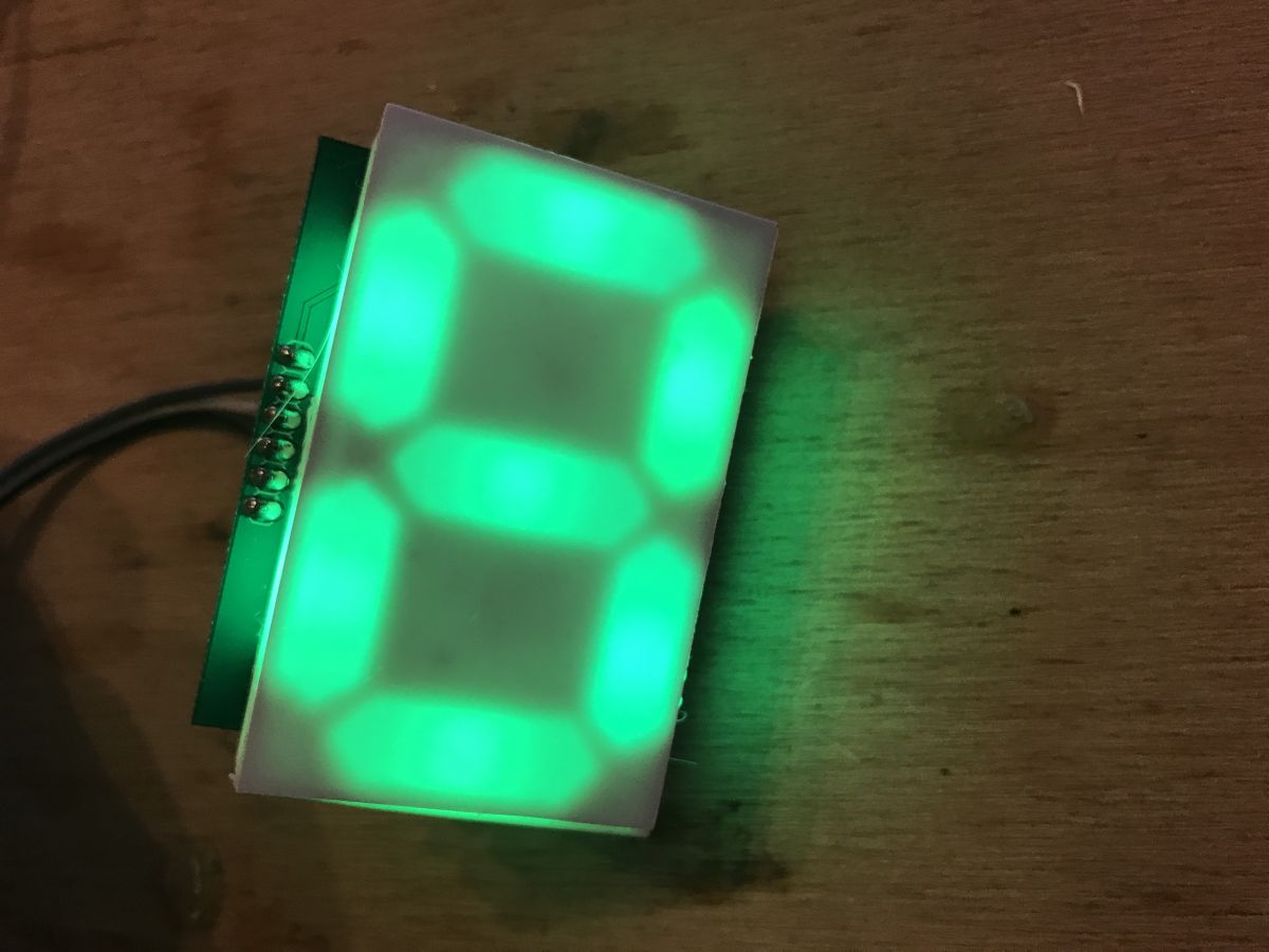
Final result:
Combining subsequent panels I designed the panels so that they could be joined together. Unfortunately, however, they turned out to have slightly too thick edges and I couldn't use the typical 2.54mm jumpers to join them, but I managed in another way. This will be corrected in the next version.
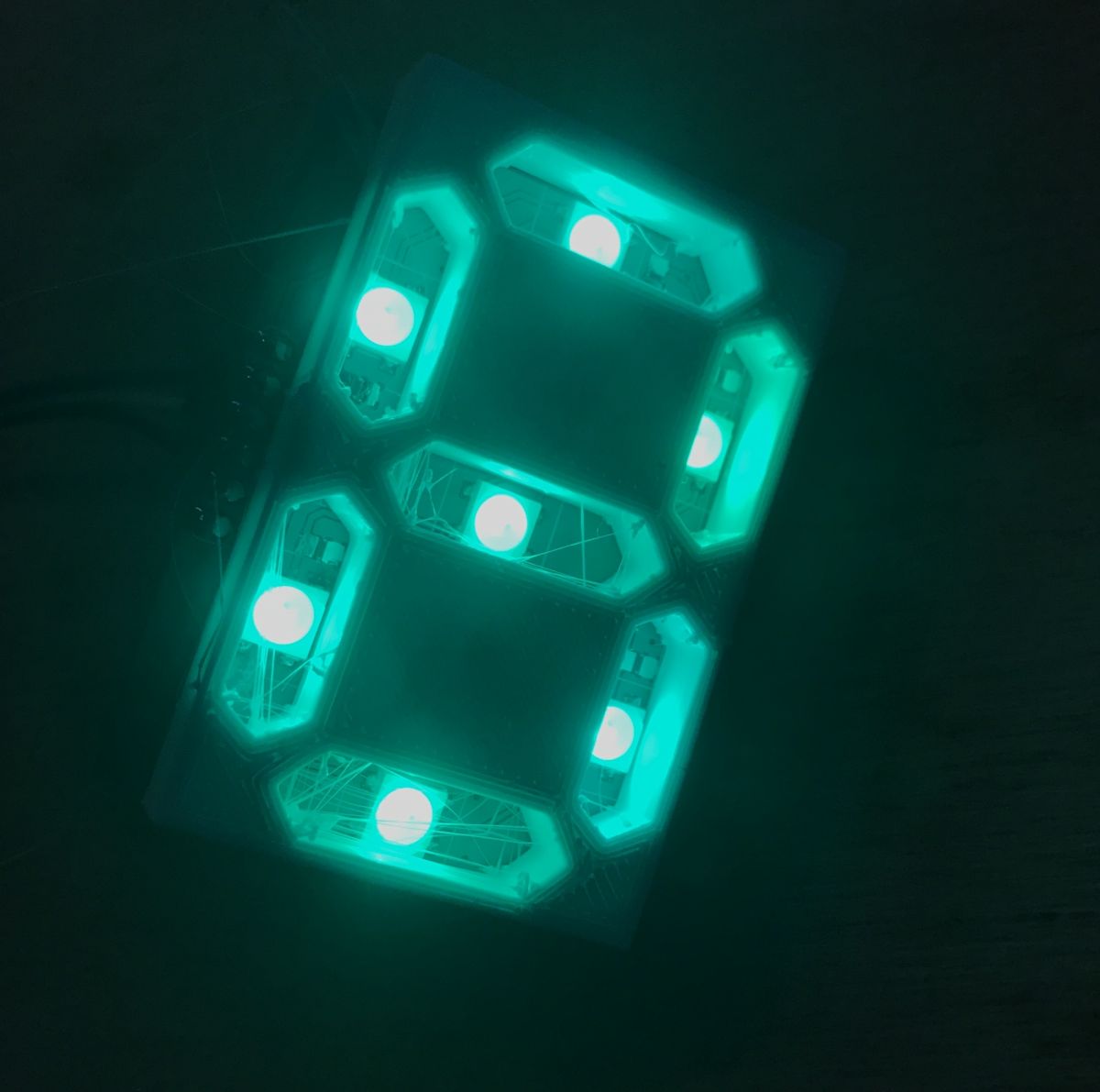
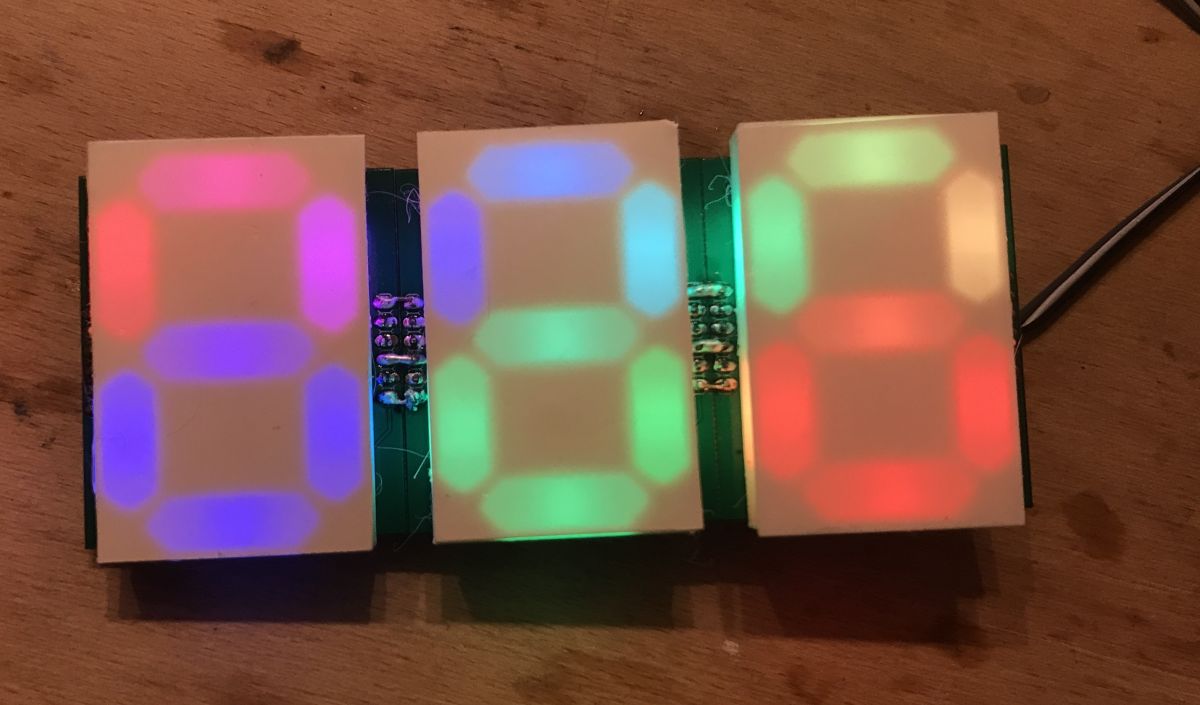
Ultimately I wanted to use the prototypes I made as a temperature display, so I connected the three modules together:
(in the meantime I also switched from Arduino UNO to Nano) The module in action (highest possible brightness):
Colour test (50% brightness):
Example operating code for Arduino (countdown) Ultimately, I intend to use my display with the PIC, but nevertheless I thought I'd write some short test code for it on the Arduino and share it with you.
The code supports digit division and you can easily add support for more digits to it.
The code is based on the Adafruit_NeoPixel library.h, from here:
https://github.com/adafruit/Adafruit_NeoPixel Copy of the repo above to download in .zip:
Adafruit_N...200911.zip (70.48 kB)You must be logged in to download this attachment. Code:
Code: C / C++
Log in, to see the code
The 'displayDigit' function sets the display of a given digit to a specific position, and 'displaySimple' displays a three-digit number (more digits can be handled, but the code must be modified). The 'masks' array specifies which parts should be lit for which digit (further elements can be added to this array to display, for example, the letter 'A').
It's worth remembering that just setting the WS2812B colour through the library here doesn't display it on the strip, to display the changes you need to call 'strip.show()'.
The result of the code:
Based on this, you can easily realise a simple thermometer or clock (in the case of the clock, the fourth digit will be useful, you will need to modify the code).
Mistakes made, what could be improved, etc This was my first attempt at making my own displays based on 3D printing, so a few things could be improved here:
- first of all, you need to improve the edges of the boards so that the goldpins would reach each other (there would be a gap of 2.54mm between them) in order to be able to connect them with ordinary two-pin jumpers
- the number of WS2812B could be doubled to increase the brightness of the segments (although they are now clearly visible)
- you could think about using the other side of the PCB, e.g. give space for the microcontroller there (but of course only use it for the first module, and not solder in the others)
- this 3D printed element could be printed with more infill or thicker, because a little bit of its side walls let the light through and they should not
- a better light diffusing coating could be used, maybe someone has an idea what kind?
- the board from the photos in the topic was obviously missing the description layer, it simply got lost during the export to Gerbers, in the next version you should remember to add it
Summary The first attempt was essentially successful - I am happy with my display. It is comfortable to use and looks good in a dark room. I will definitely make a second, improved version of it. From the version shown here, I think I will in turn make a thermometer and use the RGB possibilities to somehow also reflect the displayed temperature through the colour of the digits.
Attachments: Blender file with display model (and some additions):
my7segdisp....blend.zip (74.53 kB)You must be logged in to download this attachment. Eagle file with the display PCB (needs tweaking!):
ws2812b_7s.._10.zip (116.24 kB)You must be logged in to download this attachment.
About Author
p.kaczmarek2 wrote 14612 posts with
rating 12630 , helped 655 times.
Been with us since 2014 year.
Well, maybe not just the brightness, but the evenness of the backlighting. [Read more]
yogi009
11 Sep 2020 16:45
It's good that people are trying to create such constructions themselves. It stimulates the brain to think. [Read more]
androot
11 Sep 2020 18:21
A PCB with white soldermask would probably be more expensive, but the lighting effect would be more visible.
This printed piece with the shapes of the digits could have the recesses for the LEDs not perpendicular,... [Read more]
Piottr242
11 Sep 2020 18:48
And what I miss about this is the implementation of a microcontroller, so that this can be controlled via the normal seven segments, or in a better case via i2C.
See how you can make a module like Sparkfun... [Read more]
yogi009
11 Sep 2020 19:09
In my opinion, what is missing here is simply good 'optics', but making them at home is not easy. [Read more]
Loker
11 Sep 2020 19:09
Regarding the improvement of the uniformity of the segment surface illumination (uniformity), there are several possibilities:
- these diodes are generally not suitable for this purpose (small beam angle),... [Read more]
yogi009
11 Sep 2020 19:13
This is probably the main design obstacle and a well-made matt optic on the final surface takes care of the issue. [Read more]
Loker
11 Sep 2020 19:18
Believe me - it doesn't take care of :( In the case of a small LED-surface distance even if "bare" LED structures (bare die) are used only the appropriate resin (dissipative resin) will do. But this applies... [Read more]
yogi009
11 Sep 2020 19:28
That is why I wrote that this is difficult to achieve in an amateur setting. [Read more]
398216 Usunięty
11 Sep 2020 21:29
I have used glugan in similar situations. Simple and (stubbornly) reversible (can be hollowed out in case of "W"). [Read more]
yogi009
11 Sep 2020 21:50
Yes, it does have some effect, but it's not the same. [Read more]
Maureli73
11 Sep 2020 22:21
You can also buy ready-made ones, I use them and I think they are quite good.
https://www.rgbdigit.com/shop/index.php?id_category=12&controller=category&id_lang=1
Mariusz [Read more]
yogi009
11 Sep 2020 22:35
Except that this topic is not about bought-in displays. [Read more]
Freddy
12 Sep 2020 07:54
This price in particular is not bad :D ;)
https://obrazki.elektroda.pl/9618258100_1599889989_thumb.jpg
This is the DIY section mate, not where to buy. [Read more]
Interesting idea.
What struck me immediately was the lack of possibility to assemble the modules without gaps.
A smaller pcb and connectors on the other side of the PCB - male=>female would have... [Read more]
ArturAVS
14 Sep 2020 17:23
When making some luminous lettering I solved this in a different way. I omit the shaping of the lettering itself because here the Author printed and I milled in hard PU foam. In order to get sharp and... [Read more]
398216 Usunięty
14 Sep 2020 17:28
With these glass balls in my opinion a very cool idea. If anything, you can get them in specialty shops (larger than the "road" ones) as steriliser fillers. You can try them out. [Read more]
ArturAVS
14 Sep 2020 17:39
I used to paint roads and that's why this idea occurred to me :D First there were experiments with other materials and, for example, coarse crystal sugar also gives decent results. Such a bag would last... [Read more]
FAQ
TL;DR: DIY a color 7‑segment digit using WS2812B LEDs on a ≤5×5 cm PCB; “The first attempt was essentially successful.” Use 5 V, one data pin, and a 3D‑printed diffuser. [Elektroda, p.kaczmarek2, post #18918354]
Why it matters: This FAQ helps makers build brighter, cleaner-looking modular RGB digits for clocks, thermometers, and counters—without vendor lock‑in.
Uniformity tips: Two LEDs per segment, larger LED‑to‑face distance, and stronger diffusion improve evenness. [Elektroda, Loker, post #18918746]
What is this project in simple terms?
A modular RGB 7‑segment digit using WS2812B LEDs on a custom PCB with a 3D‑printed mask and diffuser, controlled from Arduino. [Elektroda, p.kaczmarek2, post #18918354]
How do I wire WS2812B for this digit?
Provide 5 V and GND, and feed a single DIN data line from your microcontroller. Add a small series resistor if leads are long. [Elektroda, p.kaczmarek2, post #18918354]
How do I orient WS2812B correctly during soldering?
Match the PCB’s pin‑1 dot diagonally opposite the LED’s truncated corner. Incorrect orientation prevents data passing and lighting. [Elektroda, p.kaczmarek2, post #18918354]
How can I improve segment brightness and uniformity?
Use two LEDs per segment, increase the LED‑to‑diffuser distance, or use a thicker, more diffusive film. “Two diodes per segment will improve the situation.” [Elektroda, Loker, post #18918746]
Are there other DIY diffusion methods that keep edges sharp?
Yes. Paint segment walls black, fill recesses with glass microbeads, set with clearcoat, then cover with frosted Plexi for crisp edges. [Elektroda, ArturAVS, post #18923226]
Redesign edges so 2.54 mm pins meet or place complementary connectors on opposite PCB sides to eliminate spacing gaps. [Elektroda, willyvmm, post #18919447]
What mistakes should I avoid on the next PCB spin?
Ensure 2.54 mm edge pin spacing for jumpers, add silkscreen, thicken the 3D mask walls, and consider MCU placement on the back. [Elektroda, p.kaczmarek2, post #18918354]
Should I switch to WS2811 instead of WS2812B?
WS2811 can drive several external LEDs per channel, easing diffusion by spreading emitters within each segment. [Elektroda, kaczodp, post #18929749]
What are WS2811 downsides versus WS2812B here?
WS2812B integrates WS2811 plus LEDs, simplifying layout. Using discrete WS2811 adds an IC, resistors, and extra routing. [Elektroda, Freddy, post #18929572]
Any mechanical tweaks to push optical quality further?
A white soldermask boosts reflectance, and slanted LED recesses can reflect more light into each segment window. [Elektroda, androot, post #18918672]


Comments
Well, maybe not just the brightness, but the evenness of the backlighting. [Read more]
It's good that people are trying to create such constructions themselves. It stimulates the brain to think. [Read more]
A PCB with white soldermask would probably be more expensive, but the lighting effect would be more visible. This printed piece with the shapes of the digits could have the recesses for the LEDs not perpendicular,... [Read more]
And what I miss about this is the implementation of a microcontroller, so that this can be controlled via the normal seven segments, or in a better case via i2C. See how you can make a module like Sparkfun... [Read more]
In my opinion, what is missing here is simply good 'optics', but making them at home is not easy. [Read more]
Regarding the improvement of the uniformity of the segment surface illumination (uniformity), there are several possibilities: - these diodes are generally not suitable for this purpose (small beam angle),... [Read more]
This is probably the main design obstacle and a well-made matt optic on the final surface takes care of the issue. [Read more]
Believe me - it doesn't take care of :( In the case of a small LED-surface distance even if "bare" LED structures (bare die) are used only the appropriate resin (dissipative resin) will do. But this applies... [Read more]
That is why I wrote that this is difficult to achieve in an amateur setting. [Read more]
I have used glugan in similar situations. Simple and (stubbornly) reversible (can be hollowed out in case of "W"). [Read more]
Yes, it does have some effect, but it's not the same. [Read more]
You can also buy ready-made ones, I use them and I think they are quite good. https://www.rgbdigit.com/shop/index.php?id_category=12&controller=category&id_lang=1 Mariusz [Read more]
Except that this topic is not about bought-in displays. [Read more]
This price in particular is not bad :D ;) https://obrazki.elektroda.pl/9618258100_1599889989_thumb.jpg This is the DIY section mate, not where to buy. [Read more]
Or perhaps a Fresnel lens would help? [Read more]
Interesting idea. What struck me immediately was the lack of possibility to assemble the modules without gaps. A smaller pcb and connectors on the other side of the PCB - male=>female would have... [Read more]
When making some luminous lettering I solved this in a different way. I omit the shaping of the lettering itself because here the Author printed and I milled in hard PU foam. In order to get sharp and... [Read more]
With these glass balls in my opinion a very cool idea. If anything, you can get them in specialty shops (larger than the "road" ones) as steriliser fillers. You can try them out. [Read more]
I used to paint roads and that's why this idea occurred to me :D First there were experiments with other materials and, for example, coarse crystal sugar also gives decent results. Such a bag would last... [Read more]